
Method for producing milling grooves in soil and groove wall milling device

A technology of milling device and groove wall, which is applied in excavation, earthmoving machine/shovel, mechanically driven excavator/dredging machine, etc. Daily output, the effect of efficient milling

Pending Publication Date: 2022-05-27
BAUER MASCH GMBH
View PDF6 Cites 0 Cited by
  • Summary
  • Abstract
  • Description
  • Claims
  • Application Information

AI Technical Summary

Problems solved by technology

However, other factors, such as the friction of the milling cutter at the groove walls and the way the groove is filled with support liquid, also have a non-negligible influence on this force value
In order to avoid overloading the milling wheel (which would lead to increased wear or damage to the milling teeth), corresponding safety factors must be taken into account when measuring the applied load value

Method used


Image

  • Method for producing milling grooves in soil and groove wall milling device

Examples


Embodiment Construction

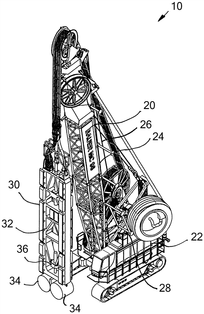
[0026] The slot wall milling device 10 according to the figure has a carrier 20 with a carrier device 22 provided with a crawler running gear. At the carrier device 22, the mast 24 is positioned approximately vertically pointing, and the carrier cable 26 is guided on the mast head of the mast.

[0027]At the free end of the carrying cable 26, a substantially known slot wall milling cutter 30 and a scaffold-like milling cutter frame 32 are suspended. The carrier cable 26 is connected to the slot wall mill 30 at the upper end thereof. The other end of the load-carrying cable 26 is led to the only sketched winch 28 at the load-carrying device 22 . The slot wall milling cutter 30 can be lifted and lowered vertically by means of the winch 28 .

[0028] A total of four milling wheels 34 are respectively arranged in pairs at the lower end of the milling cutter frame 32 of the slot wall milling cutter 30 , as shown only schematically in the figures. The milling wheel 34 can be brou...


PUM


Abstract

The invention relates to a groove wall milling device and a method for producing a milling groove in a soil, the groove wall milling device having a groove wall milling cutter and a support device, the support device being designed to lift and lower the groove wall milling cutter into the soil, the groove wall milling cutter is connected at the upper end of the groove wall milling cutter to the support mechanism and at the lower end of the groove wall milling cutter has at least one milling wheel which is rotatably mounted and can be driven in rotation by means of a rotary drive in order to remove the soil material, and wherein a target value for the feed speed of the groove wall milling cutter during removal of the soil material can be preset in the control unit, the groove wall milling cutter is controlled by the control unit to be lowered into the soil through the bearing mechanism. For efficient milling operation, the feed speed is controlled by means of the control unit as a function of the rotational speed and / or the torque of the at least one milling wheel, the feed speed of the groove-wall milling cutter being reduced compared to a target value for the feed speed when a predetermined limit value for the rotational speed and / or for the torque is reached.

Description

technical field [0001] The invention relates to a method for producing milling grooves in soil by means of a groove wall milling device having a groove wall milling cutter and a supporting means according to the preamble of claim 1 . The mechanism is configured for raising and lowering the slot wall milling cutter, wherein the slot wall milling cutter is connected at its upper end to the carrier means and at its lower end has at least one milling wheel, which is rotatably mounted and can be driven via a rotary drive Driven in rotation to remove soil material, wherein a setpoint value for the feed speed of the slot wall milling cutter when removing soil material can be preset in a control unit, which controls the movement of the slot wall milling cutter by the carrier mechanism lowered into the soil. [0002] Furthermore, the invention relates to a slot wall milling device according to the preamble of claim 10 with a slot wall milling cutter and a carrier which is designed for...

Claims


Application Information

Patent Timeline
Patent Type & Authority Applications(China)
IPC IPC(8): E02F3/20E02D17/13E02F3/24E02F5/08E02F5/14
CPCE02F3/205E02D17/13E02F3/24E02F3/246E02F5/08E02F5/145
Inventor A·胡格尔
Owner BAUER MASCH GMBH
Learn More