Transmission system of embroidery machine and embroidery machine thereof

A transmission system and embroidery machine technology, applied in the field of embroidery machines, can solve problems such as thread breakage, needle breakage, and shuttle bed coordination errors

Pending Publication Date: 2022-05-31
浙江玛雅机电科技有限公司
View PDF5 Cites 0 Cited by
  • Summary
  • Abstract
  • Description
  • Claims
  • Application Information

AI Technical Summary

Problems solved by technology

Therefore, the deflection of the middle part of the upper shaft increases, and the deflection of the middle part of the lower shaft increases, resulting in a decrease in the synchronization performance of the upper and lower shafts, and errors in the cooperation between the machine head and its corresponding shuttle bed, which in turn affect the performance of the embroidery machine, resulting in broken threads, Needle breakage, damage to the fabric to be embroidered, etc.

Method used


Image

  • Transmission system of embroidery machine and embroidery machine thereof
  • Transmission system of embroidery machine and embroidery machine thereof
  • Transmission system of embroidery machine and embroidery machine thereof

Examples


Embodiment 1

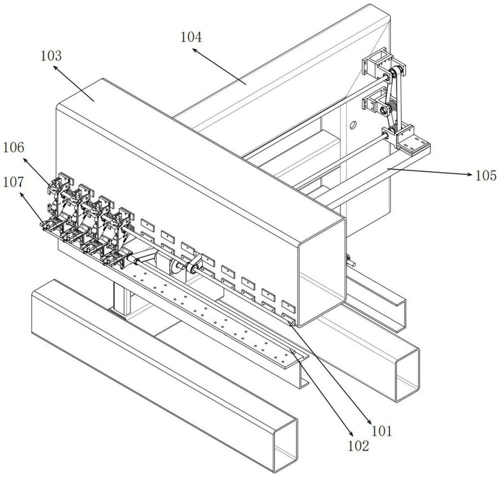
[0030] This embodiment provides a transmission system of an embroidery machine, please refer to figure 1 As shown, the embroidery machine includes an upper shaft 101, a lower shaft 102, a girder 103, a backpack frame 104, a frame 105, a number of machine heads 106 and a number of shuttle machines 107. In order to facilitate the demonstration of the transmission system of this embodiment, the figure is omitted. Part of the machine head and shuttle bed were removed.

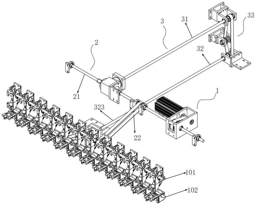
[0031] The following focuses on the transmission system of this embodiment. Please refer to figure 2 As shown, in order to facilitate the display of the transmission system, structures such as the girder, the backpack frame, the frame, etc. are omitted in the figure. The transmission system includes a driving part 1, a first transmission part 2 and a U-shaped transmission part 3. The driving part 1 and the first The transmission member 2 is drivingly connected, the first transmission member 2 and the U-shaped tra...

Embodiment 2

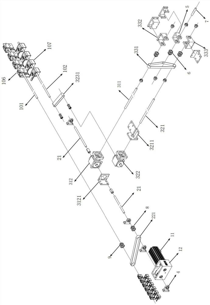
[0042] like Figure 5 As shown, this embodiment provides a transmission system for an embroidery machine. The difference from Embodiment 1 is that the second transmission member 31 includes a fourth belt 313, the third transmission member 32 includes a fifth belt 324, and the second belt assembly 33 It includes a second belt 331 and a belt transmission case 334. The belt transmission case 334 is respectively provided with a fourth transmission shaft 3341 and a fifth transmission shaft 3342. The fourth belt 313 is connected to the first transmission shaft 21 and the fourth transmission shaft 3341 through the pulley The fifth belt 324 is connected to the lower shaft 102 and the fifth transmission shaft 3342 through pulleys, respectively, and the second belt 331 is connected to the fourth transmission shaft 3341 and the fifth transmission shaft 3342 through the pulleys.

[0043] In this embodiment, the fourth belt 313 and the fifth belt 324 are also provided with a belt tensionin...

Embodiment 3

[0047] This embodiment provides an embroidery machine. The embroidery machine is installed with the transmission system of the embroidery machine in Embodiment 1 or Embodiment 2. The transmission system of the embroidery machine has been described in detail in Embodiment 1 or Embodiment 2. , which will not be repeated here.


PUM


Abstract

The invention relates to the technical field of embroidery machines, and discloses an embroidery machine transmission system and an embroidery machine thereof.The embroidery machine transmission system comprises a driving part, a first transmission part and a U-shaped transmission part, the driving part is in driving connection with the first transmission part, and the first transmission part and the U-shaped transmission part are in driving connection with an upper shaft and a lower shaft respectively; and the first transmission part is synchronously connected with the U-shaped transmission part. The upper shaft and the lower shaft are driven by the first transmission part and the U-shaped transmission part respectively, and the first transmission part and the U-shaped transmission part are in transmission connection to guarantee synchronization of the first transmission part and the U-shaped transmission part. The first transmission shaft is connected with the upper shaft through the first belt assembly to play a role in synchronizing and supporting the upper shaft, through the scheme, synchronous driving of the upper shaft and the lower shaft is achieved, and the synchronization performance of the upper shaft and the lower shaft is improved.

Description

technical field [0001] The invention relates to the technical field of embroidery machines, in particular, discloses a transmission system of an embroidery machine and an embroidery machine thereof. Background technique [0002] The embroidery machine, also known as the computerized embroidery machine, is the most advanced embroidery machine in the contemporary era. It enables the traditional manual embroidery to be realized with high speed and high efficiency, and also realizes the "multi-level, multi-functional, and unity and perfection". It is an electromechanical product that embodies a variety of high and new technologies. As computerized embroidery replaces manual embroidery, computerized embroidery machines will also become the main machine in the embroidery industry. [0003] The embroidery machine includes an upper shaft, a lower shaft, a table board, several machine heads and several shuttle beds. The heads are arranged on the upper shaft at equal intervals alon...

Claims


Application Information

Patent Timeline
IPC IPC(8): D05C11/00
CPCD05C11/00
Inventor 王立庆刘司志徐伟成周燕军
Owner 浙江玛雅机电科技有限公司
Why Eureka
Try Eureka