Fire-fighting pressure boosting and stabilizing equipment

An equipment and voltage stabilization technology, applied in drinking water installations, buildings, separation methods, etc., can solve the problems of decreased water absorption efficiency, accumulation of a large number of weeds, branches, etc., to achieve the effect of maintaining smooth flow and improving water absorption efficiency

Inactive Publication Date: 2022-05-31
马威
View PDF0 Cites 0 Cited by
  • Summary
  • Abstract
  • Description
  • Claims
  • Application Information

AI Technical Summary

Problems solved by technology

[0003] The fire boosting and voltage stabilizing equipment consists of two parts, the motor and the pump. It is a boosting and voltage stabilizing equipment dedicated to fire fighting. The pump structure includes pump body, impeller, pump cover, mechanical seal and other components. The pump and motor are coaxial. At present, there are Some fire boosting and stabilizing equipment will be installed where there is water flow. When it is running, it will absorb the water flow for use, because some water flow will contain a lot of impurities such as weeds and branches. In order to prevent them from causing blockage, it will A filter cartridge is installed at one end of the water suction pipe of the equipment body. However, after long-term use, a large amount of weeds, branches, and large solid particles will accumulate on the outer wall of the filter cartridge, resulting in a decrease in water absorption efficiency and requiring manual cleaning.

Method used


Image

  • Fire-fighting pressure boosting and stabilizing equipment
  • Fire-fighting pressure boosting and stabilizing equipment
  • Fire-fighting pressure boosting and stabilizing equipment

Examples


Embodiment 1

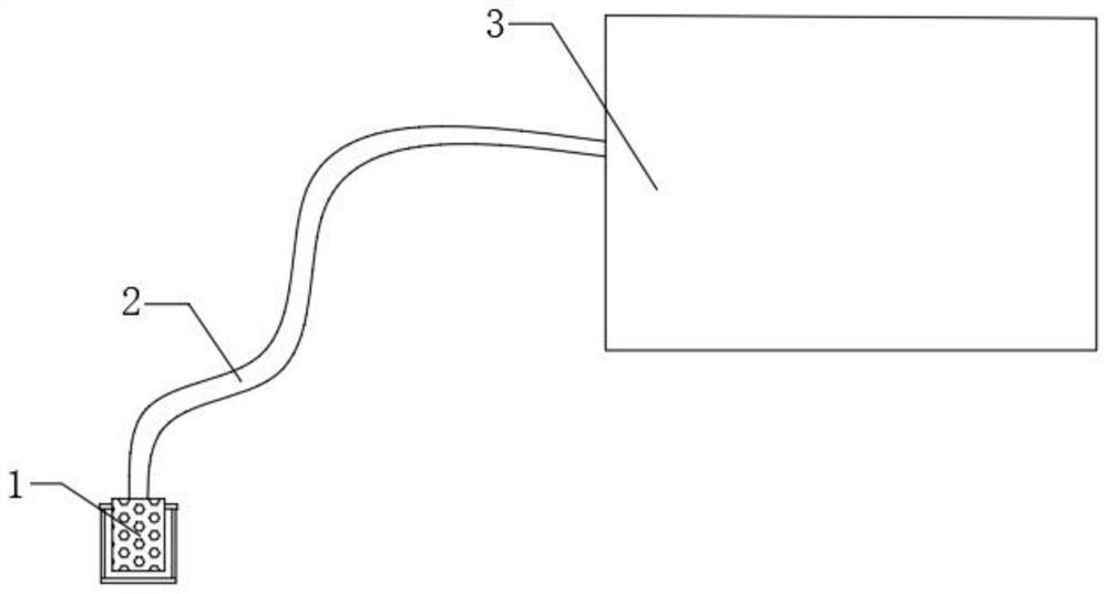
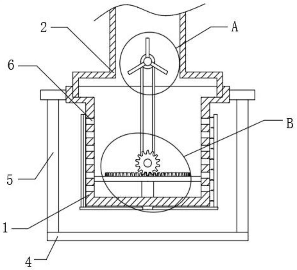
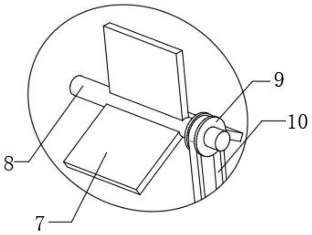
[0032] refer to Figure 1-Figure 4 , a kind of fire boosting and stabilizing equipment, comprising a device body 3, a water suction pipe 2 is provided on one side of the device body 3, and a filter cartridge 1 is provided at one end of the water suction pipe 2, and a plurality of through holes 6 are provided on the surface of the filter cartridge 1 to absorb water. The inner wall of the tube 2 is rotatably connected with a rotating shaft-8, and the outer wall of the rotating shaft-8 is fixedly connected with three drive plates 7, and the outer wall of one end of the rotating shaft-8 is fixedly connected with a pulley-9, and the outer wall of the pulley-9 is provided with a belt-10, the belt One end of one 10 is provided with a rotating mechanism, and the rotating mechanism is located inside the filter cartridge 1, the bottom of the filter cartridge 1 is rotatably connected with the rotating shaft 2 11, and the outer wall above the rotating shaft 11 is fixedly connected with thr...

Embodiment 2

[0038] refer to Figure 1-Figure 6 , a kind of fire boosting and stabilizing equipment, comprising a device body 3, a water suction pipe 2 is provided on one side of the device body 3, and a filter cartridge 1 is provided at one end of the water suction pipe 2, and a plurality of through holes 6 are provided on the surface of the filter cartridge 1 to absorb water. The inner wall of the tube 2 is rotatably connected with a rotating shaft-8, and the outer wall of the rotating shaft-8 is fixedly connected with three drive plates 7, and the outer wall of one end of the rotating shaft-8 is fixedly connected with a pulley-9, and the outer wall of the pulley-9 is provided with a belt-10, the belt One end of one 10 is provided with a rotating mechanism, and the rotating mechanism is located inside the filter cartridge 1, the bottom of the filter cartridge 1 is rotatably connected with the rotating shaft 2 11, and the outer wall above the rotating shaft 11 is fixedly connected with thr...

Embodiment 3

[0047] refer to Figure 1-Figure 8 , a kind of fire boosting and stabilizing equipment, the equipment body 3, a water suction pipe 2 is provided on one side of the equipment body 3, and a filter cartridge 1 is provided at one end of the water suction pipe 2, and a plurality of through holes 6 are opened on the surface of the filter cartridge 1, and the water suction pipe 2. The inner wall is rotatably connected with a rotating shaft-8, and the outer wall of the rotating shaft-8 is fixedly connected with three driving plates 7, and the outer wall of one end of the rotating shaft-8 is fixedly connected with a pulley-9, and the outer wall of the pulley-9 is provided with a belt-10, and a belt-1 10 is provided with a rotating mechanism at one end, and the rotating mechanism is located inside the filter cartridge 1. The bottom of the filter cartridge 1 is rotatably connected with the rotating shaft 2 11, and the outer wall above the rotating shaft 11 is fixedly connected with three ...


PUM


Abstract

The fire-fighting pressure boosting and stabilizing equipment comprises an equipment body, a water suction pipe is arranged on one side of the equipment body, a filter cartridge is arranged at one end of the water suction pipe, a plurality of through holes are formed in the surface of the filter cartridge, a first rotating shaft is rotationally connected to the inner wall of the water suction pipe, and three driving plates are fixedly connected to the outer wall of the first rotating shaft; the outer wall of one end of the first rotating shaft is fixedly connected with a first belt wheel, the outer wall of the first belt wheel is sleeved with a first belt, one end of the first belt is provided with a rotating mechanism, and the rotating mechanism is located in the filter cylinder. The outer wall of the filter cartridge can be cleaned, weeds, branches, garbage impurity particles and the like accumulated on the surface of the filter cartridge can be removed, so that the situation that through holes of the filter cartridge are blocked by the weeds, the branches, the garbage particles and the like is avoided, smooth water absorption is kept, manual cleaning is not needed, and the water absorption efficiency of the equipment body is improved.

Description

technical field [0001] The invention relates to the technical field of fire fighting equipment, in particular to a fire boosting and stabilizing equipment. Background technique [0002] Firefighting is to eliminate hidden dangers and prevent disasters (that is, the general term for preventing and solving the man-made, natural and accidental disasters that people encounter in the process of life, work and study). Of course, the narrow meaning is in the early stage of people's understanding: Meaning, and fire-fighting equipment is essential for fire-fighting. [0003] The fire boosting and voltage stabilizing equipment consists of two parts, the motor and the pump. It is a boosting and voltage stabilizing equipment dedicated to fire fighting. The pump structure includes pump body, impeller, pump cover, mechanical seal and other components. The pump and motor are coaxial. At present, there are Some fire boosting and stabilizing equipment will be installed where there is water ...

Claims


Application Information

Patent Timeline
Patent Type & Authority Applications(China)
IPC IPC(8): E03B5/00E03B3/04B01D29/33B01D29/64
CPCE03B5/00B01D29/33B01D29/64B01D29/6415B01D29/6476
Inventor 马威
Owner 马威
Why Eureka
Try Eureka