
Hollow thin-wall concrete composite column

A hollow thin-walled, concrete technology, applied in columns, pillars, piers, etc., can solve the problems of low installation efficiency, low transportation and hoisting efficiency, and solid column self-heavy, so as to improve transportation efficiency and hoisting efficiency and reduce transportation. Consistent effect of cost and energy consumption, structural integrity

Pending Publication Date: 2022-05-31
江苏万斯达建筑科技有限公司
View PDF0 Cites 0 Cited by
  • Summary
  • Abstract
  • Description
  • Claims
  • Application Information

AI Technical Summary

Problems solved by technology

[0002] In the development of domestic prefabricated buildings, the existing prefabricated concrete columns mostly use solid columns or hollow composite columns; the weight of solid columns is very large, and the efficiency of transportation and hoisting is very low; the existing hollow composite columns evacuate the prefabricated part of the columns Part of the self-weight is reduced; however, both the solid column and the hollow composite column prefabricate the stirrups and the stressed longitudinal reinforcement in the concrete, and the longitudinal reinforcement of the column is generally connected by a grouting sleeve or a threaded sleeve, and the location of the reinforcement requires It is very precise; when beams and columns are installed, conflicts between steel bars of beams and columns often occur, resulting in particularly low installation efficiency; the construction quality control of grouting sleeves is difficult, and detection methods cannot guarantee the quality of grouting sleeves is stable; once there is a column with unstable grouting quality , it is particularly difficult to reinforce in the later stage; the existing prefabricated columns are all artificially bound steel bars, which cannot reflect the advantages of building industrialization

Method used


Image

  • Hollow thin-wall concrete composite column
  • Hollow thin-wall concrete composite column
  • Hollow thin-wall concrete composite column

Examples


Embodiment

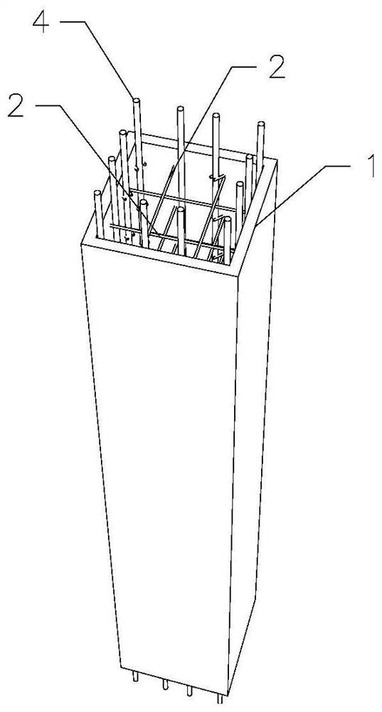
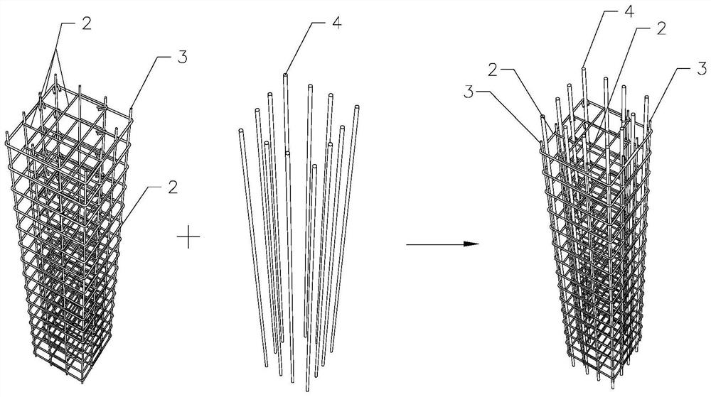
[0023] Example: see attached Figure 1-4 , the present invention provides a technical solution: a hollow thin-walled concrete composite column, which includes:

[0024] Pre-embedded steel skeleton;

[0025] The concrete shell 1, the concrete shell 1 is adapted to be wrapped on the outside of the pre-embedded steel skeleton, and the pre-embedded steel skeleton is connected with the concrete shell 1, so that the pre-embedded steel skeleton and the concrete shell 1 are fixed to form a prefabricated hollow column;

[0026] And stressed longitudinal steel bar 4, there are multiple stressed longitudinal steel bars 4, and multiple stressed longitudinal steel bars 4 are evenly inserted and bound on the inner side of the prefabricated hollow column, and connected with upper and lower column steel bars.

[0027] In this embodiment, the pre-embedded reinforcement skeleton includes stirrups 2 and erecting bars 3, several erecting bars 3 are embedded in the concrete shell 1, and several e...


PUM

PropertyMeasurementUnit
Outer wall thicknessaaaaaaaaaa

Abstract

The invention discloses a hollow thin-wall concrete composite column which comprises a pre-buried steel bar framework. The concrete shell wraps the outer side of the pre-embedded steel bar framework in a matched mode, the pre-embedded steel bar framework is connected with the concrete shell, so that the pre-embedded steel bar framework and the concrete shell are fixed to form the prefabricated hollow column, and after the prefabricated hollow column is transported to a site, longitudinal steel bars are inserted into the prefabricated hollow column in a penetrating mode and then hoisted in place. And finally, concrete is poured to form the concrete composite column. In the assembling production process, the operation process is simple and convenient, and factory manufacturing is easy to achieve; in the on-site construction process, components are light and extremely easy to hoist, longitudinal load-bearing steel bars are inserted on site, a prefabricated concrete shell is thin, the contradictions that longitudinal steel bars of a traditional prefabricated concrete column are complex in connection, the steel bars are prone to dislocation and the like are avoided, prefabricated components are light in self weight and extremely easy and convenient to transport and hoist, a large amount of cast-in-place concrete is adopted, and prefabricated part concrete is thin; and the overall shape of the component is very good.

Description

technical field [0001] The invention specifically relates to the technical field of construction engineering, in particular to a hollow thin-walled concrete composite column. Background technique [0002] In the development of domestic prefabricated buildings, the existing prefabricated concrete columns mostly use solid columns or hollow composite columns; the weight of solid columns is very large, and the efficiency of transportation and hoisting is very low; the existing hollow composite columns evacuate the prefabricated part of the columns Part of the self-weight is reduced; however, both the solid column and the hollow composite column prefabricate the stirrups and the stressed longitudinal reinforcement in the concrete, and the longitudinal reinforcement of the column is generally connected by a grouting sleeve or a threaded sleeve, and the location of the reinforcement requires It is very precise; when beams and columns are installed, conflicts between steel bars of b...

Claims


Application Information

Patent Timeline
IPC IPC(8): E04C3/34E04C5/06
CPCE04C3/34E04C5/0622
Inventor 赵洪波
Owner 江苏万斯达建筑科技有限公司
Learn More