Supercharge Your Innovation With Domain-Expert AI Agents!

Wire clamp for electric power circuit wire

A technology for power lines and wire clips, which is applied to overhead lines/cable equipment, etc., can solve the problems of easily damaged ropes, easy to slide, and ropes that cannot be fixed at a fixed point, so as to achieve the effect of modularization.

Pending Publication Date: 2022-05-31
河南瑞凡恩新能源科技有限公司
View PDF0 Cites 1 Cited by
  • Summary
  • Abstract
  • Description
  • Claims
  • Application Information

AI Technical Summary

Problems solved by technology

[0006] The invention provides a wire clamp for power line wires, which solves the problems that the existing power line maintenance cannot achieve fixed-point positioning and fixation due to the direct contact between the rope and the wires, and is prone to slipping and easy damage to the ropes and wires.

Method used


Image

  • Wire clamp for electric power circuit wire
  • Wire clamp for electric power circuit wire
  • Wire clamp for electric power circuit wire

Examples


Embodiment 1

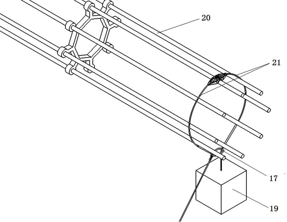
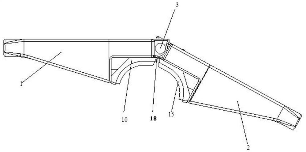
[0037] as Figure 1-Figure 5 As shown, the present embodiment provides a power line wire clamper, comprising a left clamp support frame 1, a right clamp support frame 2 and a sandwich module for clamping the wire 20, the left clamp support frame 1 and the right clamp support frame 2 are connected by rotation of the hinge 3, the hinge 3 jacket has an elastic reset device, the left clamp module and the right clamp module relative to the axis 3 symmetrical setting, the left clamp support frame 1 and the right clamp support frame 2 are provided with a through hole for the static rope 21 to pass through 4, The clamp module is located on the downward one side of the left sandwich support frame 1 and the right clamp support frame 2.

[0038] Wherein, the left sandwich support frame 1 and the right sandwich support frame 2 of the present embodiment

[0039]Left sandwich support frame 1 and right sandwich support frame 2 are hollow design, left sandwich support frame 1 and right clamp suppo...

Embodiment 2

[0049] as Figure 6 、 Figure 7 As shown, the present embodiment provides a power line wire clamper, comprising a left clamp support frame 1, a right clamp support frame 2 and a clamp module for clamping the wire, the left clamp support frame 1 and the right clamp support frame 2 are connected by the rotation of the hinge 3, the hinge 3 jacket has an elastic reset device, the left clamp module and the right clamp module are symmetrically set relative to the shaft 3, the left clamp support frame 1 and the right clamp support frame 2 are provided with a through hole for the static rope 21 to pass through 4, The clamp module is located on the upper and lower symmetrical sides of the left sandwich support frame 1 and the right clamp support frame 2. The connecting surface of the left sandwich support frame 1 and the right clamp support frame 2 is provided with a notch at both ends, the clamping module comprises a clamping module 10, the clamping module 10 is fixed within the notch.

[0...


PUM

PropertyMeasurementUnit
Elastic modulusaaaaaaaaaa

Abstract

The invention, which belongs to the technical field of the power maintenance equipment, discloses an electric power circuit wire clamping device comprising a left wire clamping support frame, a right wire clamping support frame and a clamping block module used for clamping a wire, the left wire clamping support frame and the right wire clamping support frame are rotatably connected through a rotating shaft, and the rotating shaft is sleeved with an elastic reset device. The left wire clamping module and the right wire clamping module are symmetrically arranged relative to the rotating shaft, the left wire clamping supporting frame and the right wire clamping supporting frame are respectively provided with a through hole for a static force rope to penetrate through, and the clamping block module is located on one side or two sides of the left wire clamping supporting frame and the right wire clamping supporting frame. According to the wire clamp, a hanging point can be conveniently and effectively fixed, a wire can be protected from being damaged in the operation process, the practicability is greatly improved through the modular design, the structure adopts the hollowed-out design, the structure weight is reduced, the total weight of the structure is controlled within 2 kg on the premise that the requirement for the load of 500 kg is met, and the service life of the wire clamp is prolonged. And a guarantee is provided for hoisting the light portable unmanned aerial vehicle on line.

Description

Technical field [0001] The present invention relates to the technical field of power maintenance equipment, specifically a power line wire clamper. Background [0002] As an important part of the power system, power lines undertake tasks such as the transportation and distribution of electric energy, which are affected by complex environmental climate during operation, and are prone to some failures, so it is necessary to do a good job in the maintenance of power lines, reduce the probability of failure and improve the safe operation level of the power grid. [0003] When power line maintenance requires personnel or equipment to lift from the ground to high into the wire through a soft ladder or rope, it is usually by hooking a dump truck or connecting the rope directly across the wire to the wire, the main disadvantages of this situation are: [0004] 1. The contact point between the dumping bucket trolley and the rope across the wire and the wire cannot be firmly fixed in a spe...

Claims


Application Information

Patent Timeline
IPC IPC(8): H02G1/02
CPCH02G1/02
Inventor 郑尚高陈勇
Owner 河南瑞凡恩新能源科技有限公司
Features
  • R&D
  • Intellectual Property
  • Life Sciences
  • Materials
  • Tech Scout
  • Unparalleled Data Quality
  • Higher Quality Content
  • 60% Fewer Hallucinations
Learn More