Sound insulation box for testing

A sound insulation and box technology, applied in the direction of electrical components, etc., can solve the problems of restricting test efficiency, inability to accurately adjust products according to needs, and long waiting time for testing

Pending Publication Date: 2022-06-03
GOERTEK INC
View PDF0 Cites 0 Cited by
  • Summary
  • Abstract
  • Description
  • Claims
  • Application Information

AI Technical Summary

Problems solved by technology

After the door of the existing sound insulation box is closed, it is a closed environment, and the power supply and communication lines cannot enter and leave the box with the product, so the pre-test preparation and post-processing work can only be carried out in the box; resulting in the product testing process can only be: Place the first product in the box—preparation for the test—acoustic test—post-processing—take out the first product—place the second product in the box—preparation for the test—acoustic test—post-processing—take out the second product ...; It can be seen that in a test cycle, the operator spends a lot of time on picking and placing the product, pre-test preparation and post-processing, that is, the test waiting time is long, which seriously restricts the improvement of test efficiency
[0003] In addition, at present, most of the doors on the sound insulation box are rotary doors, and an effective seal cannot be formed between the box door and the box body, that is, the ideal sound insulation environment cannot be improved.
Furthermore, when testing the acoustic performance of some electronic products, the product needs to be placed in the center of the box or at a specific position to obtain a more realistic performance index; the current sound insulation boxes have poor versatility and cannot accurately adjust the product according to needs The position can only be determined according to the operator's human eye observation, which affects the consistency of the test process

Method used


Image

  • Sound insulation box for testing
  • Sound insulation box for testing
  • Sound insulation box for testing

Examples


Embodiment Construction

[0039] In order to make the object, technical solution and advantages of the present invention clearer, the present invention will be further described in detail below in conjunction with the accompanying drawings and embodiments. It should be understood that the specific embodiments described here are only used to explain the present invention, not to limit the present invention.

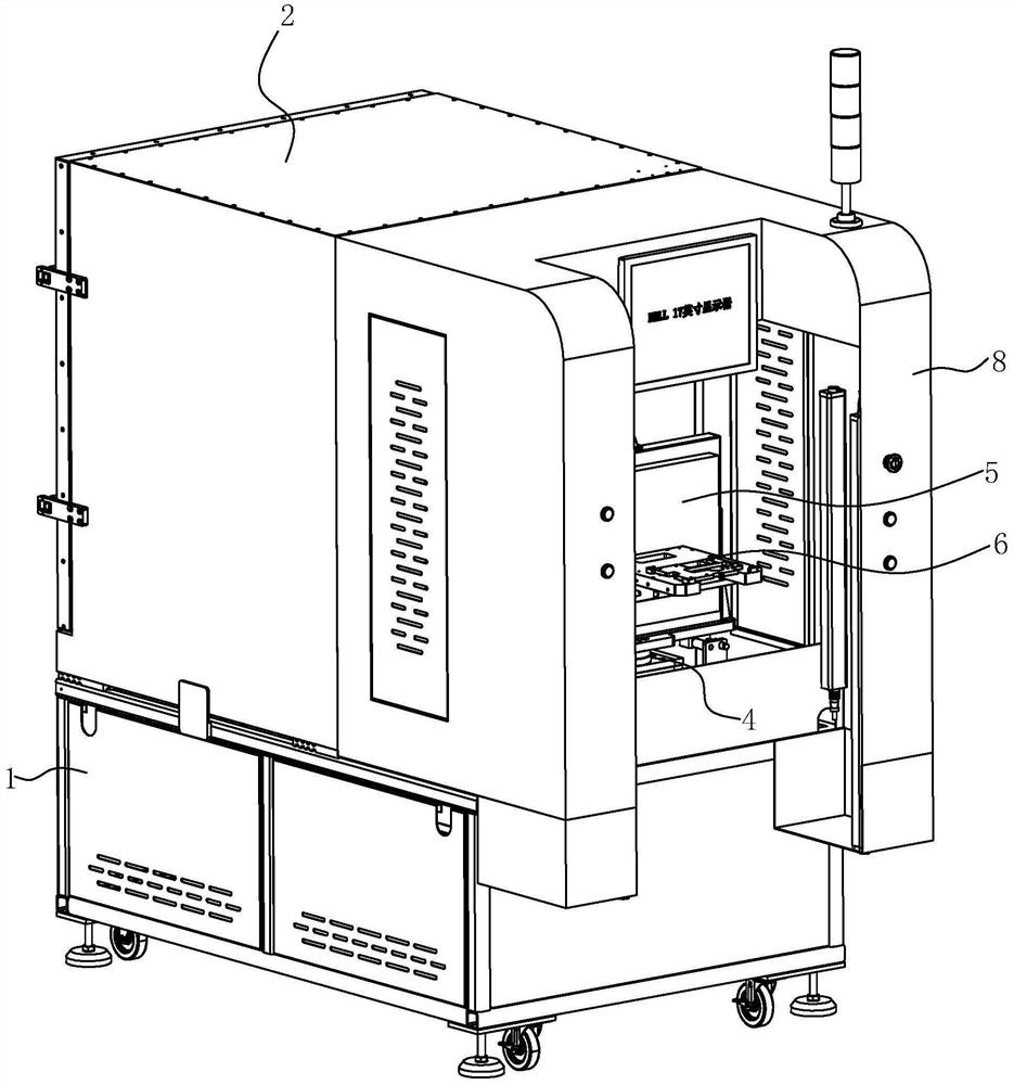
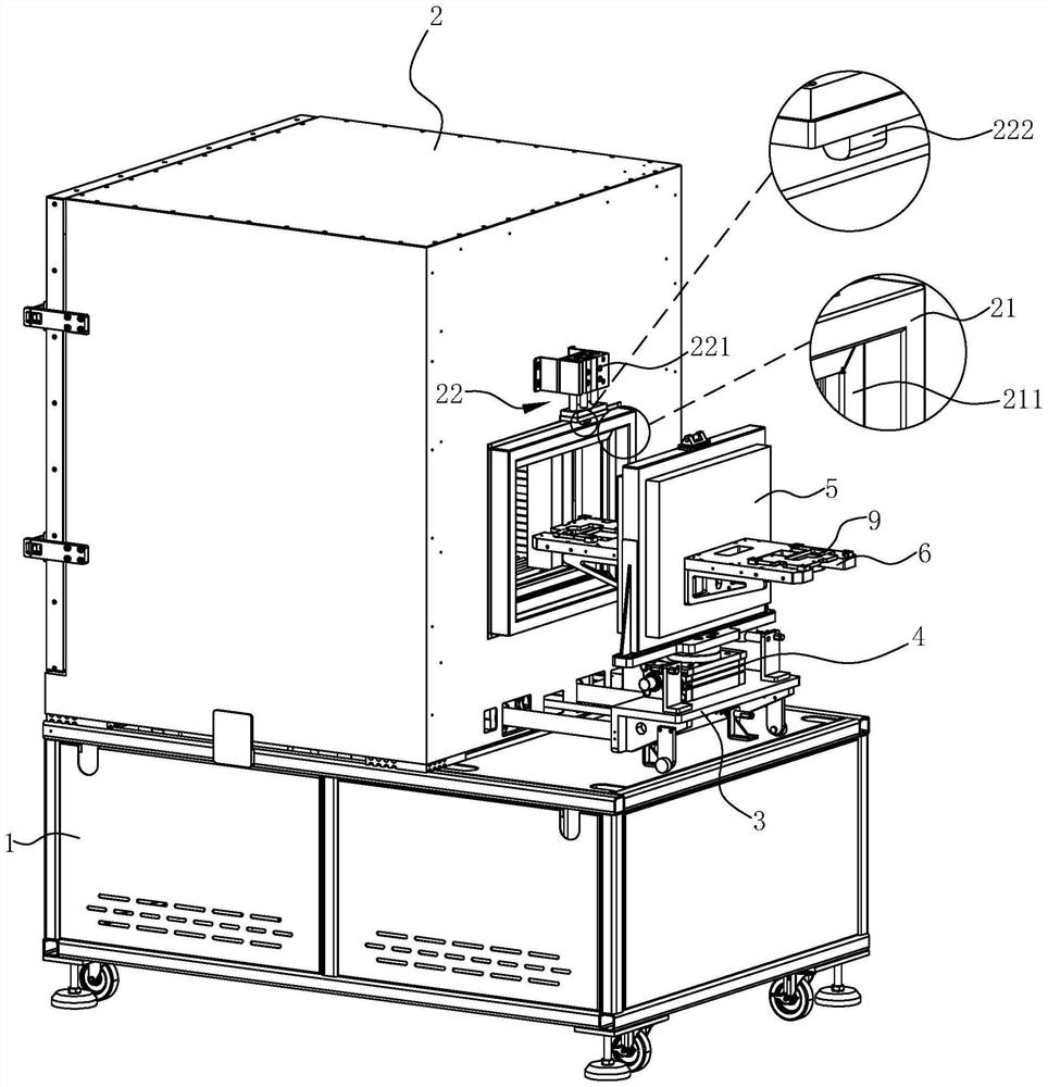
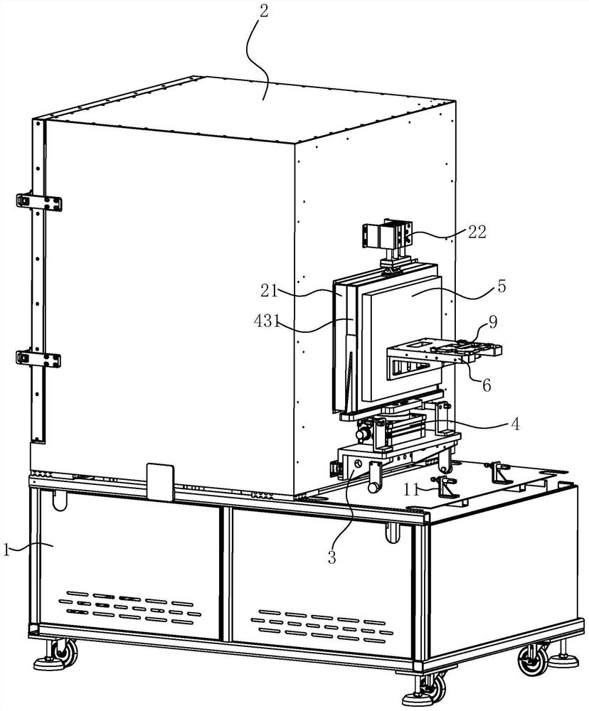
[0040] Depend on Figure 1 to Figure 3Commonly shown, this embodiment discloses a sound insulation box for testing, which specifically includes a platform 1 (built-in control cabinet and cables) and a box body 2 arranged on the platform 1, and the box body 2 is provided with a front door frame structure twenty one. In addition, it also includes a front door horizontal movement mechanism 3 arranged on the platform 1 and a front door rotation mechanism 4 arranged on the horizontal movement part of the front door horizontal movement mechanism 3; The front door 5 arranged and used to seal fit with th...


PUM


Abstract

The invention discloses a sound insulation box for testing, which comprises a stand and a box body arranged on the stand, and is characterized in that the box body is provided with a front door frame structure; the front door horizontal moving mechanism is arranged on the stand; the front door rotating mechanism is arranged on a horizontal moving part of the front door horizontal moving mechanism; the front door rotating mechanism is at least provided with two front doors which are arranged in the rotating direction and used for being matched with the front door frame structure in a sealing mode, and the front doors are provided with product bearing and positioning mechanisms. And the horizontal moving part of the front door horizontal moving mechanism, the front door rotating mechanism and the front door are provided with wire passing holes for a product power supply communication cable to pass through. A product power supply communication cable can enter and exit from the box body along with a product through the wire passing hole; and the time of taking, placing, power supply starting and communication operation outside one product box is overlapped with the test time inside the other product box, so that the test waiting time is shortened, and the test efficiency is improved.

Description

technical field [0001] The invention belongs to the technical field of acoustic testing, in particular to a sound insulation box for testing. Background technique [0002] Household electronic products such as smart speakers and doorbells usually need to conduct acoustic performance tests in an ideal sound insulation environment before leaving the factory; at present, sound insulation boxes are mainly used to provide ideal sound insulation environments. Generally, household products do not contain batteries. Before the test, it is necessary to perform pre-test preparations such as plugging in the power cord and communication line, and starting the machine. After that, the acoustic test is performed. . After the door of the existing sound insulation box is closed, it is a closed environment, and the power supply and communication lines cannot enter and leave the box with the product, so the pre-test preparation and post-processing work can only be carried out in the box; res...

Claims


Application Information

Patent Timeline
IPC IPC(8): H04R29/00
CPCH04R29/00
Inventor 张鲁彬吴海雯臧洪志耿红光陈军生宿博强刘鲁丹
Owner GOERTEK INC
Why Eureka
Try Eureka