Battery system for electric vehicle, method for diagnosing battery system, and electric vehicle

A battery system and electric vehicle technology, applied in the field of electric vehicles, can solve problems such as voltage measurement difficulties and achieve the effect of improving diagnostic coverage

Pending Publication Date: 2022-06-03
ROBERT BOSCH GMBH
View PDF2 Cites 0 Cited by
  • Summary
  • Abstract
  • Description
  • Claims
  • Application Information

AI Technical Summary

Problems solved by technology

Due to the higher output voltage of the battery, direct voltage measurement between the poles of the battery is difficult

Method used


Image

  • Battery system for electric vehicle, method for diagnosing battery system, and electric vehicle
  • Battery system for electric vehicle, method for diagnosing battery system, and electric vehicle
  • Battery system for electric vehicle, method for diagnosing battery system, and electric vehicle

Examples


Embodiment Construction

[0037] In the following description of embodiments of the present invention, identical or similar elements are denoted by the same reference numerals, wherein repeated descriptions of these elements are omitted in individual cases. The drawings show only schematically the subject-matter of the invention.

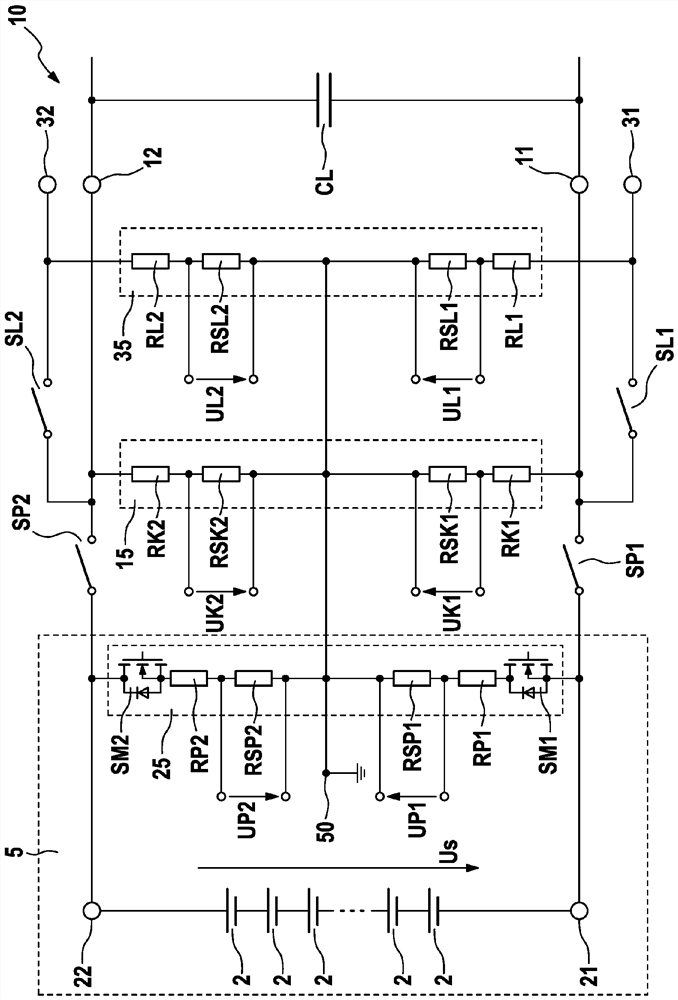
[0038] figure 1 A schematic diagram of a battery system 10 for an electric vehicle is shown. The battery system 10 includes a battery pack 5 having a positive electrode 22 , a negative electrode 21 and a plurality of battery cells 2 . The battery cells 2 are here connected in series between the positive electrode 22 and the negative electrode 21 . A system voltage Us is applied between the poles 21 , 22 of the battery pack 5 , which system voltage is supplied by the battery cells 2 connected in series. The system voltage Us is, for example, 400V.

[0039] The battery system 10 also includes a coupled grid. The coupled grid has a negative terminal 11 and a positive termi...


PUM


Abstract

The invention relates to a battery system (10) for an electric vehicle, comprising: a battery pack (5) having a positive electrode (22), a negative electrode (21), at least one battery cell (2) and a pack voltage divider (25); and at least one coupling network having a negative connection (11) and a positive connection (12), wherein the group voltage divider (25) comprises a positive group resistor (RP2) and a positive sub-group resistor (RSP2), which are connected in series with each other between the positive electrode (22) and a reference point (50), and a negative group resistor (RP1) and a negative sub-group resistor (RSP1), which are connected in series with each other between the negative electrode (21) and the reference point (50). The at least one coupling network has a coupling voltage divider (15), the coupling voltage divider comprises a positive coupling resistor (RK2) and a positive partial coupling resistor (RSK2), which are connected in series with each other between the positive connection (12) and the reference point (50), and a negative coupling resistor (RK1) and a negative partial coupling resistor (RSK1), which are connected in series with each other between the negative connection (11) and the reference point (50). The invention also relates to a method for diagnosing a battery system (10) according to the invention, wherein a positive group voltage (UP2) occurring at the positive component-group resistor (RSP2) is measured, a negative group voltage (UP1) occurring at the negative component-group resistor (RSP1) is measured, a positive coupling voltage (UK2) occurring at the positive component-coupling resistor (RSK2) is measured, a negative coupling voltage (UK1) occurring at the negative component-coupling resistor (RSK1) is measured, and the measured voltages (UP1, UP2, UK1, UP2, UK1, UP2, UK1, UK2, UK1, UK1, UK2, UK1, UK2, UK1, UK2, UK1, UK2, UK1, UK2, UK1, UK2, UK1, UK2, UK1, UK2, UK1, UK2, UK1, UK2, UK1, UK2, UK1, UK2, UK1 The invention also relates to an electric vehicle comprising a battery system (10) according to the invention.

Description

technical field [0001] The invention relates to a battery system for an electric vehicle, the battery system comprising: a battery pack having a positive electrode, a negative electrode, at least one battery cell and a group voltage; and at least one coupled grid, the The coupled grid has a negative terminal and a positive terminal, wherein the group voltage divider includes a positive group resistance and a positive group-group resistance connected in series with each other between the positive pole and the reference point and connected in series with each other to the negative pole and the reference point. Negative group resistance and negative group resistance between reference points. The invention also relates to a method for diagnosing a battery system according to the invention and an electric vehicle comprising the battery system according to the invention. Background technique [0002] It is gradually becoming apparent that in the future more and more motor vehicle...

Claims


Application Information

Patent Timeline
IPC IPC(8): G01R31/327H02J7/00B60L50/60
CPCG01R31/3275H02J7/0036H02J7/0019H02J7/0063B60L50/60G01R31/3835G01R31/396G01R19/16542G01R31/006Y02E60/10Y02T10/70
Inventor C·齐瓦诺普洛斯T·夏德利希J·斯沃博达
Owner ROBERT BOSCH GMBH
Why Eureka
Try Eureka