Combined type clamping mechanism for internal fixation of spine

A clamping mechanism and combined technology, applied in the field of medical devices, can solve the problems of inability to quickly adapt to human conditions, large application limitations, and inability to disassemble the spinal internal fixation device, so as to reduce application limitations and effectively The effect of fixed support

Active Publication Date: 2022-06-07
CHANGZHOU GEASURE MEDICAL DEVICES CO LTD
View PDF9 Cites 0 Cited by
  • Summary
  • Abstract
  • Description
  • Claims
  • Application Information

AI Technical Summary

Problems solved by technology

[0006] Aiming at the deficiencies of the prior art, the present invention provides a combined clamping mechanism for internal fixation of the spine, which solves the problem that the existing internal fixation devices for the spine do not have detachability, resulting in the inability to quickly adapt to human conditions and relatively limited application. big problem

Method used


Image

  • Combined type clamping mechanism for internal fixation of spine
  • Combined type clamping mechanism for internal fixation of spine
  • Combined type clamping mechanism for internal fixation of spine

Examples


Embodiment 1

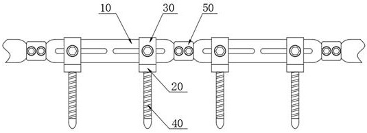
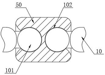
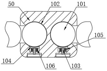
[0034] see Figure 1-7 As shown in the figure, a combined clamping mechanism for internal fixation of the spinal column includes a plurality of fixing rods 10, a connecting column 50 is provided between the opposite ends of two adjacent fixing rods 10, and the two sides of the connecting column 50 are respectively connected with the two One end of each fixed rod 10 is rotatably connected, and two movable components are symmetrically arranged inside the connecting column 50, and the two movable components are respectively fixedly connected with one end of the two fixed rods 10. The surface of the fixed rod 10 is symmetrically provided with two movable components. Block 30, and the inside of the fixed rod 10 is provided with an adjustment component, the bottom of the two movable blocks 30 is provided with a connecting block 20, and the interior of the two connecting blocks 20 is provided with a steering component, and the bottom of the steering component is provided with a suppor...

Embodiment 2

[0038] In the present invention, the back of the movable block 30 is rotatably provided with a limit screw 201, and one end of the limit screw 201 is rotated with a limit block 202. The limit block 202 is located in the interior of the movable block 30 and is slidably connected, and the interior of the movable block 30 is provided with a The sliding hole 203 matched with the fixing rod 10;

[0039] The adjustment assembly includes an adjustment screw 204 that is rotatably disposed on the fixed rod 10, and an adjustment wheel 205 is provided on one side of the surface of the adjustment screw 204, wherein the top of the adjustment wheel 205 extends above the fixed rod 10; the interior of the fixed rod 10 is slidably provided with a a sliding block 206, and the interior of the sliding block 206 is threadedly connected with the surface of the adjusting screw 204, the front surface of the sliding block 206 extends to the front surface of the fixed rod 10, and the front surface of th...

Embodiment 3

[0042] In the present invention, the steering assembly includes a rotating block 301 , a rotating groove 302 is formed inside the connecting block 20 to match the rotating block 301 , and the surface of the rotating block 301 is rotatably connected with the interior of the rotating groove 302 , and the interior of the rotating block 301 is provided with a rotating groove 302 . The connecting groove 303 is provided with a rotating rod 304 inside the connecting groove 303, one end of the support column 40 is fixedly connected with the surface of the rotating rod 304, and one end of the supporting column 40 is located in the interior of the connecting groove 303.

[0043] A second chute 305 is opened inside the connecting block 20, and a second positioning block 306 is slidably disposed inside the second chute 305. A second screw 307 is rotatably provided on one side of the connecting block 20, and the second screw 307 is slidably arranged. One end is rotatably connected with one ...


PUM


Abstract

The invention relates to the technical field of medical instruments, in particular to a combined type clamping mechanism for internal fixation of the spine, which comprises a plurality of fixing rods, and a connecting block is arranged between the opposite ends of two adjacent fixing rods. The included angle between the two fixing rods is easily changed through rotation of the movable balls in the movable grooves, then the fixing rods can effectively fix and clamp spines with different bending radians, then the movable balls in the movable grooves are positioned through the first positioning blocks, the included angle between the two fixing rods is fixed, and the spine fixing device is convenient to use. The fixing rods fixed through the included angle are matched with the supporting columns to fix and clamp the spine of a patient, the assembling number of the fixing rods can be selected according to the spine of the patient in different postures, the fixing and clamping device for the spine can be flexibly assembled, and the application limitation of an existing fixing and clamping device in the spine is effectively reduced.

Description

technical field [0001] The invention relates to the technical field of medical devices, in particular to a combined clamping mechanism for spinal internal fixation. Background technique [0002] In today's life, due to the high work pressure of most people, especially those who work in a sitting and standing state for a long time, the incidence of spinal diseases is particularly prominent. Long-term spinal diseases will seriously affect people's health. At the same time, in the current life Among them, when there is a disease in the spine, the surgical treatment is generally the most thorough to solve the spinal disease. However, the surgical treatment will touch a variety of nerves in the spine. Improper handling will cause the failure of the operation. Therefore, it is necessary to use equipment to clamp and correct the spine. Spinal internal fixation devices have been widely used in the clinical treatment of thoracolumbar fractures, spinal tumors, spinal deformity correct...

Claims


Application Information

Patent Timeline
Patent Type & Authority Applications(China)
IPC IPC(8): A61B17/70
CPCA61B17/7047A61B17/7064A61B17/7002A61B2017/564Y02E10/50
Inventor 蒋晓丰王佳景
Owner CHANGZHOU GEASURE MEDICAL DEVICES CO LTD
Why Eureka
Try Eureka