Fire-fighting robot with prolonged service life
A fire-fighting robot, life-span technology, applied in the cleaning method using liquid, unmanned aerial vehicle, cleaning method using tools, etc., to reduce the effect of being smashed by heavy objects
Active Publication Date: 2022-06-10
徐州鲁班智能科技有限公司
View PDF4 Cites 0 Cited by
- Summary
- Abstract
- Description
- Claims
- Application Information
AI Technical Summary
Problems solved by technology
[0004] The purpose of the present invention is to solve the problems in the prior art, when the fire-fighting robot puts out the fire of the aerial building, it is easy to be caught by the heavy objects falling from the building. In the event of a hit, since the flying rotors of the existing fire-fighting robots are all exposed outside, the flying rotors that are hit by the hit will often have damage of different sizes, and when the flying rotors are damaged, the fire-fighting robot will fall under the action of gravity. , fall from a high altitude, it is easy to cause the fire robot to break down, which reduces the service life of the fire robot, and a fire robot with improved service life is proposed
Method used
View moreImage
Smart ImageViewing Examples
Examples
Embodiment 1
Embodiment 2
Embodiment 3
Login to View More PUM
 Abstract
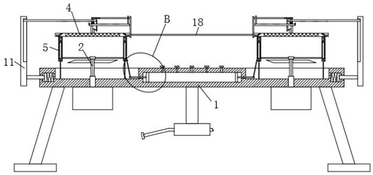
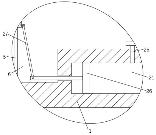
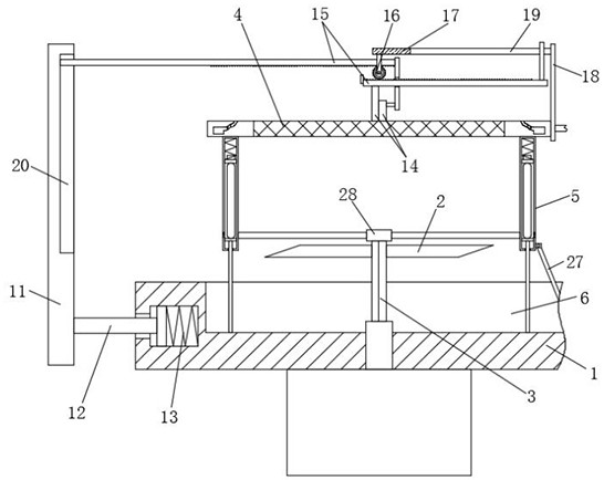
The fire-fighting robot comprises a fire-fighting robot body, a plurality of flying rotary blades are arranged at the four corners of the upper side of the fire-fighting robot body, telescopic rotating shafts are fixedly installed on the flying rotary blades, motors are fixedly installed at the lower ends of the telescopic rotating shafts, and the motors are fixedly installed at the lower end of the fire-fighting robot body; a protective net plate is arranged on the upper sides of the flying rotary blades, and a plurality of telescopic rods are fixedly installed on the outer side of the lower end of the protective net plate. When the unmanned aerial vehicle is used and the impact force of a heavy object is too large, the inner top end of the telescopic rod can be attached to the switch button, the switch button is pressed to enable the motor to stop working, the flying rotary blades stop rotating, the air bag can be crushed, the telescopic rod and the protective net plate descend, the telescopic rod descends to drive the bearing to descend, and the bearing drives the telescopic rotating shaft to contract; and the flying rotary vane is shrunk into the protection groove, so that the flying rotary vane can be well protected, and the flying rotary vane is prevented from being smashed by a heavy object.
Description
Technical field [0001] The invention involves the field of fire protection device technology, especially a fire robot that improves the service life. Background technique [0002] "Firefighting" is to eliminate hidden dangers and prevent disasters (that is, to prevent and solve the general term of people encountered by people in life, work, and study.The meaning of the fire. [0003] In existing technologies, when fire robots are extinguished by fire in the air building, they are easily smashed by the heavy objects falling in the building. Because the flying rotation leaves of the existing fire robots are naked outside, the hit flying spinLeaf often causes damage to different sizes. When the flying leaves are damaged, the fire robot will fall from the level of gravity and fall from high altitude, which will easily cause the fire robot to break and reduce the service life of the fire robot. Invention content [0004] The purpose of the present invention is to solve the existing t...
Claims
Login to View More Application Information
Patent Timeline
 Patent Type & Authority Applications(China)
IPC IPC(8): A62C3/02B08B1/00B08B3/02B08B15/04B08B17/00B64C27/08B64C27/20B64C27/32B64D45/00
CPCB64C27/08B64C27/20B64C27/32B64D45/00B08B1/006B08B1/008B08B3/02B08B15/04B08B17/00A62C3/0214A62C3/0242B64U10/10B64U2101/00
Inventor 刘洁洁
Owner 徐州鲁班智能科技有限公司
Features
- R&D
- Intellectual Property
- Life Sciences
- Materials
- Tech Scout
- Unparalleled Data Quality
- Higher Quality Content
- 60% Fewer Hallucinations
Learn More Browse by: Latest US Patents, China's latest patents, Technical Efficacy Thesaurus, Application Domain, Technology Topic, Popular Technical Reports.
© 2025 PatSnap. All rights reserved.Legal|Privacy policy|Modern Slavery Act Transparency Statement|Sitemap|About US| Contact US: help@patsnap.com


