

Driving device with belt take-up function and belt take-up method
A driving device and functional technology, applied in the direction of measuring devices, vehicle testing, machine/structural component testing, etc.
Active Publication Date: 2022-06-10
CATARC AUTOMOTIVE QUALITY INSPECTION CENT NINGBO
View PDF16 Cites 0 Cited by
- Summary
- Abstract
- Description
- Claims
- Application Information
AI Technical Summary
Problems solved by technology
However, due to the long length of the belt, the belt is also scattered after collection, taking up a lot of space, and it is easy to forget to bring it
Method used
View moreImage
Smart ImageViewing Examples


Examples
Embodiment 1
Embodiment 2
Login to View More PUM
 Abstract
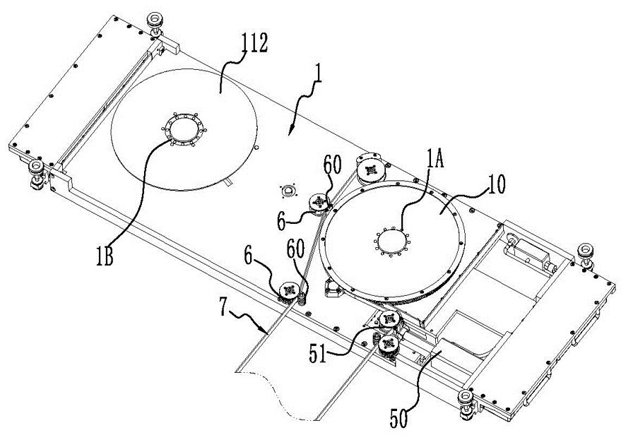
The invention relates to the technical field of automobile testing devices, and discloses a driving device with a belt take-up function and a belt take-up method.The driving device comprises a mounting frame, a belt pulley, a belt take-up wheel, a driving device, a driving device, a driving device and a belt take-up device, the mounting frame is provided with a first mounting position and a second mounting position respectively, and the belt pulley is arranged at the first mounting position while the belt take-up wheel is arranged at the second mounting position; a first connecting structure is arranged on the belt pulley, and a second connecting structure is arranged on the belt collecting wheel; the driving motor is provided with a third connecting structure, and the third connecting structure can be connected to the first connecting structure, so that the driving motor can drive the belt pulley; the third connecting structure can be connected to the second connecting structure, so that the driving motor can drive the take-up wheel; and the switching mechanism is arranged on the mounting frame and can drive the driving motor to be switched between the first mounting position and the second mounting position. The driving device has the advantages that the driving motor of the driving device not only can drive the belt for testing, but also can provide power for furling the belt, and the driving device is dual-purpose, simple in switching between two modes and high in stability.
Description
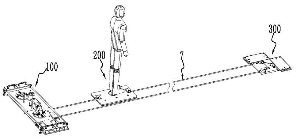
technical field [0001] The invention relates to the technical field of automobile testing devices, in particular to a driving device with a tape-rewinding function and a tape-rewinding method. Background technique [0002] Automatic Emergency Braking (AEB) can perform emergency braking on the car when an obstacle suddenly appears in front of the car to avoid a collision or reduce the speed of the collision. Frontal collisions of cars account for a high proportion of traffic accidents. The automatic emergency braking system (AEB) can effectively reduce the damage of cars and personnel and improve pedestrian safety. For vehicles equipped with an automatic emergency braking system (AEB), it is necessary to test the AEB system before the vehicle is launched to ensure that it can play an effective role during the use of the vehicle. [0003] The AEB test system mainly includes a driving device, a dummy target module and a corner device. One end of the belt is connected to the du...
Claims
Login to View More Application Information
Patent Timeline
 Patent Type & Authority Applications(China)
IPC IPC(8): G01M17/007B65H75/44
CPCG01M17/007B65H75/4486
Inventor 李海斌吴云兵朱晓勇韩飞徐军辉李兵马文博王博通李振中应宇汀王晓亮徐良陈伟艳
Owner CATARC AUTOMOTIVE QUALITY INSPECTION CENT NINGBO