
A method of realizing PCB core board positioning by magnetic field

A core board and magnetic field technology, which is applied in the orientation of circuit board tools, multi-layer circuit manufacturing, printed circuits, etc., can solve the problems of high skill requirements of personnel, insufficient punching accuracy of equipment, and difficult control of employees' subjective wishes, so as to solve the problem of hole punching. The impact of bit accuracy and the effect of improving personnel efficiency

Active Publication Date: 2022-07-29
圆周率半导体(南通)有限公司
View PDF3 Cites 0 Cited by
  • Summary
  • Abstract
  • Description
  • Claims
  • Application Information

AI Technical Summary

Problems solved by technology

[0006] Defects and deficiencies of the existing technology: the punching accuracy of the equipment is insufficient, the insertion of the core plate into the pin requires high personnel skills, the subjective will of the employees is not easy to control, and the risk of core plate damage and slippage is high

Method used

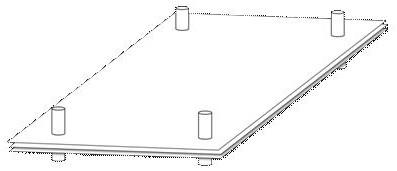

Image

  • A method of realizing PCB core board positioning by magnetic field
  • A method of realizing PCB core board positioning by magnetic field
  • A method of realizing PCB core board positioning by magnetic field

Examples


Embodiment 1

[0037] Example 1: as figure 2 and 3 shown

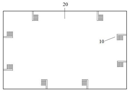
[0038] Step 1. Board edge positioning graphic design: Provide the board edge pattern requirements to the design department, add the required graphic lines to the inner Gerber data of the non-customer graphics, and each board edge of the core board 20 is provided with 2 inner layer graphics line 10;

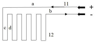
[0039] The inner layer pattern circuit 10 includes two parts, the positive and negative leads 11 and the positioning coil 12. The inner layer pattern circuit 10 is in the shape of a comb, and the positive and negative leads 11 constitute the comb back, the positioning coil 12 and the adjacent The comb groove formed between the comb teeth is formed; wherein, the length a of the comb back is 400-480 mil, the width b of the comb back is 40 mil, the width c of the comb teeth is 40 mil, and the width d of the comb groove is 40 mil.

[0040] Step 2. Inner layer pattern circuit production: including pretreatment, film sticking, exposure, de...


PUM


Abstract

The present invention provides a method for realizing PCB core board positioning by using a magnetic field, comprising the following steps: making an inner layer graphic circuit on the edge of the core board, the inner layer graphic circuit comprising a positioning coil and positive and negative leads connected to the positioning coil; Multiple fabricated core boards and prepregs are stacked alternately in turn; current is passed to the positioning coil through the positive and negative leads, and the current direction of the adjacent positioning coils is the same; the core board and the prepreg are bonded by hot-melt curing. together. Based on the principle of electromagnetic induction, the invention realizes the mutual attraction between the core boards of each layer, so as to play a role in positioning, and solves the problem that due to the insufficient drilling precision of the equipment, the core board inserting the pins requires high personnel skills, and the subjective wishes of the employees are not easy to control. , the risk of sleeve breaking is high, and the risk of core board slippage is high.

Description

technical field [0001] The invention relates to the technical field of printed circuit processing, in particular to a method for realizing PCB core board positioning through a magnetic field. Background technique [0002] With the development of electronic information technology, more and more fields use multi-layer PCB. Compared with conventional circuit boards, high-level circuit boards have thicker components, more layers, denser lines and vias, larger unit size, thinner dielectric layers, etc., internal space, interlayer alignment, impedance control and reliability. In order to overcome the above problems, the interlayer positioning accuracy of the pressing section is particularly important. [0003] Commonly used interlayer positioning methods mainly include: four-slot positioning (Pin LAM), hot melt, riveting, hot melt and rivet combination. Different product structures use different positioning methods. For high-rise boards, the Pin positioning method is usually use...

Claims


Application Information

Patent Timeline
Patent Type & Authority Patents(China)
IPC IPC(8): H05K3/46
CPCH05K3/4644H05K3/0008
Inventor 章恒何静安龙能水陈定康盛从学吴鹏杨子璐
Owner 圆周率半导体(南通)有限公司
Learn More