A valve core gland automatic assembly device

An automatic assembly and gland technology, applied in metal processing equipment, metal processing, manufacturing tools, etc., can solve problems such as low assembly accuracy, arm soreness, and inaccurate installation of valve core glands.

Inactive Publication Date: 2019-02-22
陈琼瑜
View PDF9 Cites 0 Cited by
  • Summary
  • Abstract
  • Description
  • Claims
  • Application Information

AI Technical Summary

Problems solved by technology

The existing gland installation method is to put the gland on the bottom of the faucet shell, and then manually tighten the gland screw into the faucet shell. This manual tightening method has low assembly efficiency and low assembly efficiency. The operation is cumbersome, time-consuming, labor-intensive, high labor cost, low assembly accuracy and other defects. At the same time, the arm will be very sore after manual rotation for a long time, which will lead to occupational diseases over time.
[0003] As a result, there is an assembly machine for spool gland assembly on the faucet housing on the market, as announced by the State Intellectual Property Office on April 17, 2013, and the announcement number is CN202877846U A kind of faucet spool gland When working, place the spool gland in the faucet body, then install the faucet body with the spool gland installed on the clamp seat, start the cylinder, when the lock sleeve is in contact with the spool gland The stepper motor is started, and the lock sleeve drives the valve core gland to rotate, and finally realizes the automatic screw installation of the valve core gland; although this torque assembly device solves the defects caused by traditional manual assembly, the valve core The gland is directly placed in the faucet body and then screwed. In this way, if the valve core gland is not placed flat when the valve core gland is manually placed in the faucet body, it will easily cause the installation of the valve core gland to be inaccurate, or even When the lock sleeve is rotated, the valve core gland is twisted. At the same time, the size of the lock sleeve is fixed, so that the whole device can only be assembled with a single specification of the valve core gland, and the scope of application is narrow.

Method used


Image

  • A valve core gland automatic assembly device
  • A valve core gland automatic assembly device
  • A valve core gland automatic assembly device

Examples


Embodiment Construction

[0026] The present invention will be further described below in conjunction with the accompanying drawings and specific embodiments.

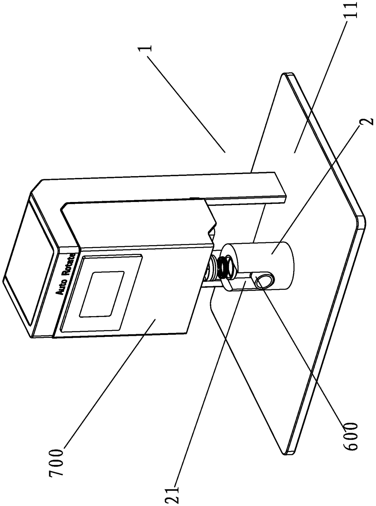
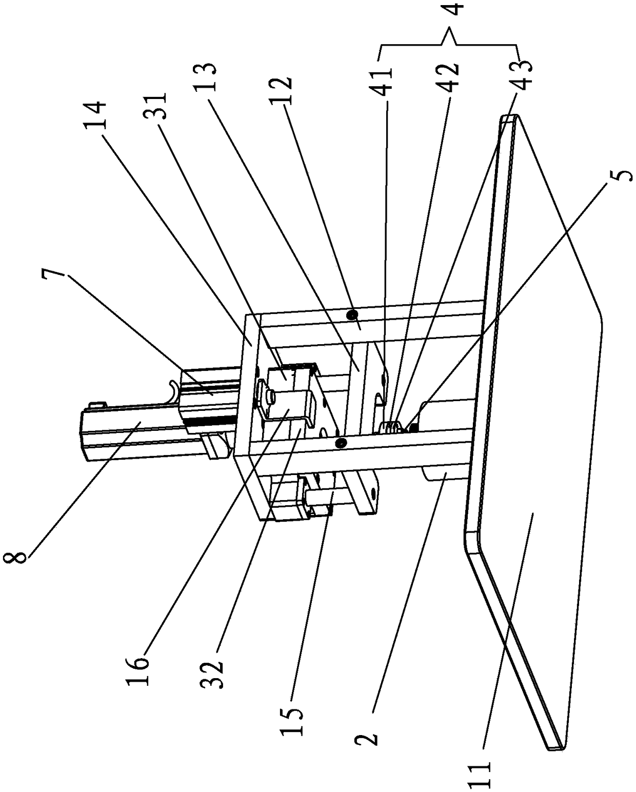
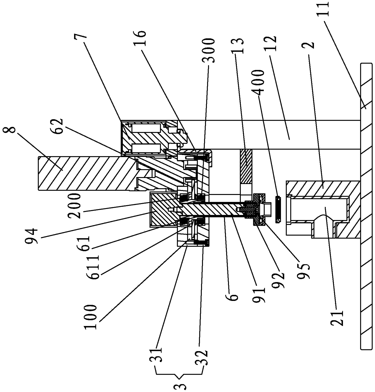
[0027] A kind of valve core gland automatic assembly device of the present invention, such as Figure 1-4 As shown, it includes a working frame 1, a faucet workpiece master mold 2 and a gland workpiece fixture device; wherein,

[0028] The working frame 1 has a working platform 11 and a vertical frame erected on the working platform 11. The faucet workpiece former 2 is in a cylindrical structure. The mold 2 is provided with a faucet placement cavity 21 whose upper end is open, for the faucet housing to be embedded in or removed from the outside; specifically: the top surface of the faucet workpiece master 2 is concavely provided with a cylindrical longitudinal Chamber, the front side wall of the faucet workpiece master 2 is recessed from the front to the radial direction of the faucet workpiece master 2. The cylindrical transverse chamber exte...


PUM


Abstract

The invention provides an automatic valve element pressing cover assembling device which comprises a working frame provided with a working platform and an upright frame, a faucet workpiece template and a pressing cover workpiece clamp device. The pressing cover workpiece clamp device comprises an elastic propping type clamp used for clamping or loosening a valve element pressing cover, an upper mounting seat capable of moving up and down, a lower mounting seat for mounting the elastic propping type clamp, and a transmission shaft, wherein the upper end of the transmission shaft is in rotary fit with the upper mounting seat, and the lower end of the transmission shaft is fixed to the lower mounting seat, and the upper mounting seat is provided with a rotation driving device for driving the transmission shaft to rotate. The transmission shaft is internally provided with a connecting rod, a propping ejector core for propping the elastic propping type clamp, and an isolating bearing located between the connecting rod and the propping ejector core. Compared with the prior art, the automatic valve element pressing cover assembling device achieves automatic assembling of the valve element pressing cover without manual operation, the assembling efficiency is high, the valve element pressing cover is precisely assembled and prevented from being damaged by torsion, and the assembling range is wide.

Description

technical field [0001] The invention relates to an assembly device, in particular to an automatic assembly device for a flash core gland. Background technique [0002] In the plumbing industry, some of the single-hole vegetable basin faucets have a zinc alloy shell. The difference between the single-hole faucet with this material shell and the traditional single-hole faucet with other material shells is that the valve core is made from It is installed at the bottom and needs to be covered with a gland with internal and external threads after installation. The existing gland installation method is to put the gland on the bottom of the faucet shell, and then manually tighten the gland screw into the faucet shell. This manual tightening method has low assembly efficiency and low assembly efficiency. The operation is cumbersome, time-consuming, labor-intensive, high labor cost, low assembly accuracy and other defects. At the same time, the arm will be very sore after manual rot...

Claims


Application Information

Patent Timeline
Patent Type & Authority Patents(China)
IPC IPC(8): B23P19/00B23P19/04
CPCB23P19/001B23P19/04
Inventor 陈琼瑜
Owner 陈琼瑜
Why Eureka
Try Eureka