Multi-interface high-speed optical fiber transmission device and method

A fiber optic transmission, multi-interface technology, applied in the direction of fiber optic transmission, transmission monitoring, transmission system, etc., can solve the problems of unfavorable equipment compatibility and common use, difficult to expand the number of channels, hardware resource consumption, etc., to reduce the complexity of system cable connection degree, reduce system redundancy, and reduce the cost of hardware cables

Pending Publication Date: 2022-06-17
CHINA ELECTRONIC TECH GRP CORP NO 38 RES INST
View PDF0 Cites 1 Cited by
  • Summary
  • Abstract
  • Description
  • Claims
  • Application Information

AI Technical Summary

Problems solved by technology

If the test results of each channel are connected to the back-end data processing equipment through a cable, the system connection will be complicated and a large amount of hardware resources will be consumed. On the other hand, once multiple one-to-one data links are formed, it will be difficult to expand The number of channels is not conducive to equipment compatibility and general use

Method used


Image

  • Multi-interface high-speed optical fiber transmission device and method
  • Multi-interface high-speed optical fiber transmission device and method
  • Multi-interface high-speed optical fiber transmission device and method

Examples


Embodiment 1

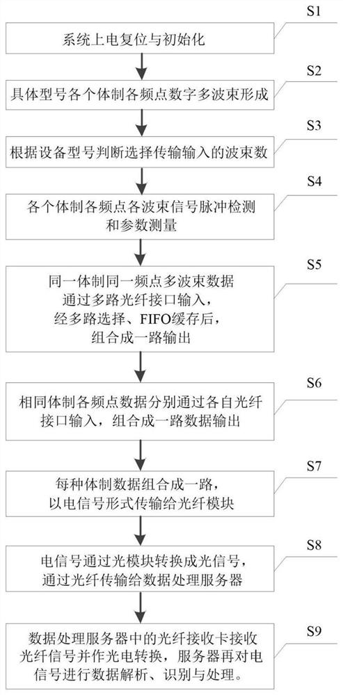
[0073] Taking an electronic detection and identification system covering M systems and each system including J frequency points as an example, the signal received by the array antenna includes M kinds of systems and each system includes J frequency points. According to the reconnaissance distance and coverage index, the signal of each frequency point has N beams.

[0074] (1) Perform digital multi-beam forming on the digitized baseband signal output by the receiving front end at each frequency point, and each frequency point generates N beams, so that M*J*N beams are generated in the system in this embodiment. Specifically, according to the system index, the number of beams at different frequency points will be different. Here, for the convenience of description, the number of beams at different frequency points is uniformly expressed as N.

[0075] (2) Perform signal detection and parameter measurement on M*J*N beam data respectively, and prepare to send it to back-end data p...

Embodiment 2

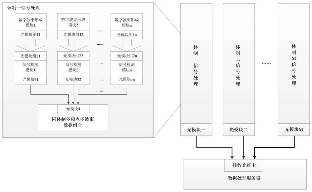
[0086] This embodiment provides a multi-interface high-speed optical fiber transmission device, including a digital signal processing module, an optical module, an optical fiber cable, and a data processing server. The schematic diagram of the system device is as follows: figure 2 shown.

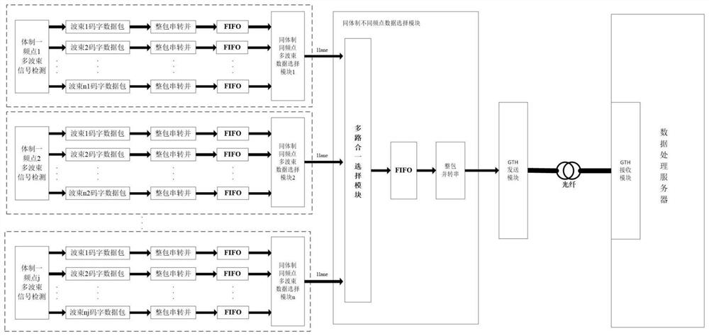
[0087] Taking an electronic reconnaissance system covering a single system, that is, an M value of 1 and J frequency points as an example, the signal received by the array antenna of the system includes one system and the system includes J frequency points. According to the reconnaissance distance and coverage index, the signal of each frequency point has N beams.

[0088] (1) The array antenna receives external signals, and after the receiving front end performs frequency conversion and digital processing, it outputs multi-channel baseband digital signals to the digital signal processing module.

[0089](2) The digital signal processing module performs digital beamforming, signal detectio...


PUM


Abstract

The invention discloses a multi-interface high-speed optical fiber transmission device and method. The multi-interface high-speed optical fiber transmission device comprises a digital signal processing module, an optical module, an optical fiber cable and a data processing server, the digital signal processing module is used for completing digital beam forming and parameter measurement of the received baseband signal; a result of the signal processing module is accessed to a data processing server through an optical module and an optical fiber cable for further signal identification; the optical module completes electro-optical conversion between the electric signal sent by the digital signal processing module and the optical signal transmitted in the optical fiber cable, and photoelectric conversion between the optical signal transmitted in the optical fiber cable and the electric signal received by the data processing server; according to the invention, on the premise of not changing the architecture of the back-end data processing server, the receiving front-end module is expanded; and meanwhile, on the premise of not losing data, multiple channel outputs are combined into one channel for transmission, so that the system redundancy is reduced, the hardware resource utilization rate is improved, and the hardware cost and the system unit design complexity are effectively reduced.

Description

technical field [0001] The invention relates to the technical field of digital signal processing, in particular to a multi-interface high-speed optical fiber transmission device and method. Background technique [0002] Modern electronic reconnaissance systems can monitor enemy military facilities, land, sea and air radio equipment around the clock and provide us with intelligence information. The reconnaissance equipment has many application scenarios and wide frequency band coverage. The types of its platforms are increasingly diverse, and the number of access data channels is increasing. In the reconnaissance system, the signal processing front-end needs to detect multi-beam data of various systems, modes and frequency bands, so the output detection results are composed of multi-channel data. If each test result is connected to the back-end data processing equipment through a cable, the system connection will be complicated, resulting in a lot of hardware resource consum...

Claims


Application Information

Patent Timeline
Patent Type & Authority Applications(China)
IPC IPC(8): H04Q9/00H04B10/25H04B17/00
CPCH04Q9/00H04B10/25H04B17/00H04Q2209/30
Inventor 王颖万卫华张银兵黄俊园寇韵涵杜旭华卢玉杰贺文干许昊天丁浩李佩琳
Owner CHINA ELECTRONIC TECH GRP CORP NO 38 RES INST
Why Eureka
Try Eureka