Novel pulsed eddy current thickness measuring device and method

A pulsed eddy current and thickness measurement technology, used in measuring devices, electromagnetic measuring devices, electrical devices, etc., can solve problems such as unfavorable field applications, inability to detect ferromagnetic materials and non-ferromagnetic materials, and complicated operations, and achieve efficient positioning. and quantitative metal loss, high-precision scanning, and the effect of no couplant

Pending Publication Date: 2022-06-24
GUANGDONG INSPECTION & RES INST OF SPECIAL EQUIP ZHUHAI INSPECTION INST +1
View PDF0 Cites 0 Cited by
  • Summary
  • Abstract
  • Description
  • Claims
  • Application Information

AI Technical Summary

Problems solved by technology

[0004] However, due to the different magnetic permeability of materials, the signal characteristics and research methods of pulsed eddy currents of ferromagnetic materials and non-ferromagnetic materials are not the same
Unlike ferromagnetic materials, which generally use the inflection point time or late signal decay rate in the logarithmic coordinate system as the characteristic value, non-ferromagnetic materials generally use the peak value, peak time, zero-crossing time or lift-off crossing point of the differential signal as the characteristic value. Eigenvalues; among these eigenvalues, the differential peak value, peak time, etc. will be affected by the lift-off height. Although the lift-off intersection point is not affected by the lift-off height, the operation is complicated, which is not conducive to field application
The difference in signal characteristics and research methods limits the application range of pulsed eddy current detectors. Most of the existing pulsed eddy current detection systems cannot simultaneously detect ferromagnetic materials and non-ferromagnetic materials.

Method used


Image

  • Novel pulsed eddy current thickness measuring device and method
  • Novel pulsed eddy current thickness measuring device and method
  • Novel pulsed eddy current thickness measuring device and method

Examples


Embodiment Construction

[0026] This part will describe the specific embodiments of the present invention in detail, and the preferred embodiments of the present invention are shown in the accompanying drawings. Each technical feature and overall technical solution of the invention should not be construed as limiting the protection scope of the invention.

[0027] In the description of the present invention, the meaning of several is one or more, the meaning of multiple is two or more, greater than, less than, exceeding, etc. are understood as not including this number, above, below, within, etc. are understood as including this number. If it is described that the first and the second are only for the purpose of distinguishing technical features, it cannot be understood as indicating or implying relative importance, or indicating the number of the indicated technical features or the order of the indicated technical features. relation.

[0028] In the description of the present invention, unless other...


PUM


Abstract

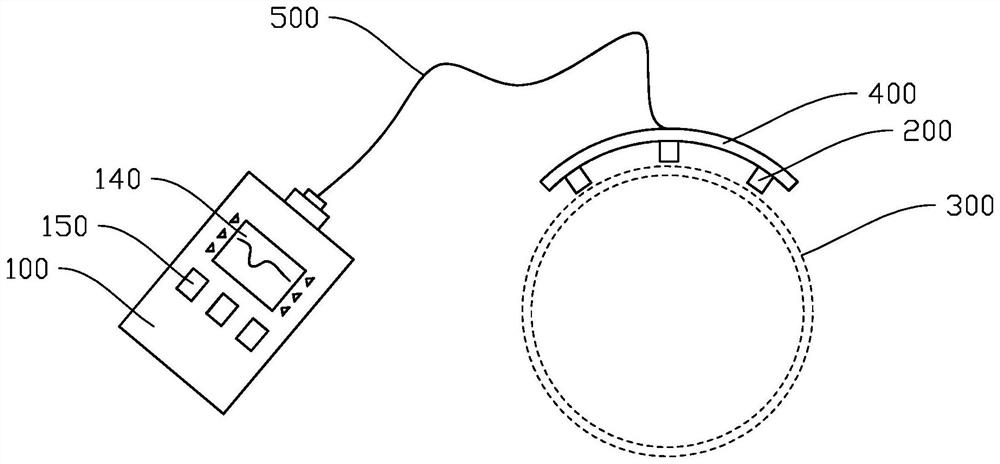
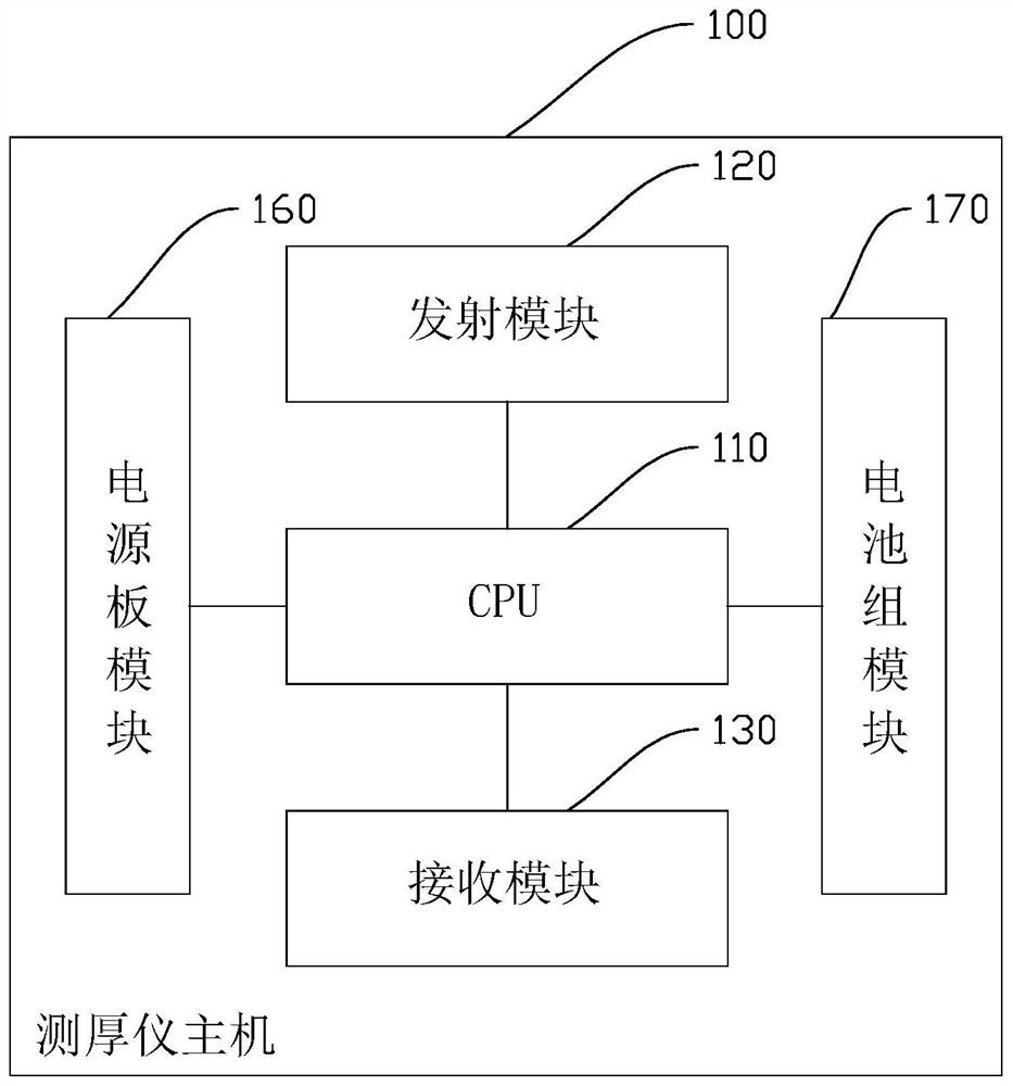
The invention discloses a novel pulsed eddy current thickness measuring device and a novel pulsed eddy current thickness measuring method. The novel pulsed eddy current thickness measuring device comprises a thickness gauge host and at least one probe, the thickness gauge host comprises a CPU, and a transmitting module and a receiving module which are electrically connected with the CPU. The probe is electrically connected with the thickness gauge host and comprises a transmitting coil and a receiving coil, the transmitting coil is used for exciting a pulsed eddy current signal for the to-be-measured pipeline, and the receiving coil is used for receiving a feedback signal of the to-be-measured pipeline. The novel pulsed eddy current thickness measuring device is portable and efficient, utilizes the low and medium frequency electromagnetic principle, does not need to polish a metal body, does not need a coupling agent, is resistant to high temperature and low temperature, achieves high-precision scanning and efficient positioning and quantification of metal loss, and then provides accurate data for completely evaluating potential safety hazards caused by internal local corrosion.

Description

technical field [0001] The invention relates to the technical field of pipeline detection, in particular to a novel pulsed eddy current thickness measuring device and method. Background technique [0002] The conventional ultrasonic thickness measurement technology (usually piezoelectric ultrasonic) that is widely used currently needs to remove the paint on the surface of the steel pipe, grind out the metal body, and need a couplant to measure the wall thickness. Although this method has high precision, the detection efficiency is very low, and the coverage rate is very small. [0003] Using pulsed eddy current testing technology to perform scanning-type wall thickness detection on metal pipes or equipment (forming current wall thickness A scan, wall thickness continuous extension value B scan, and area area C scan) is a kind of technology developed in recent years. New non-contact non-destructive testing technology. Different from the conventional eddy current detection t...

Claims


Application Information

Patent Timeline
Patent Type & Authority Applications(China)
IPC IPC(8): G01B7/06
CPCG01B7/10
Inventor 蔡勤孔令昌戚政武陈英红谢小娟郭欣欣杨宁祥向安来园凯
Owner GUANGDONG INSPECTION & RES INST OF SPECIAL EQUIP ZHUHAI INSPECTION INST
Why Eureka
Try Eureka