Transformer-coupled guidewire system and method of use

a transformer-coupled guidewire and power supply technology, which is applied in the field of guidewire power supply systems and methods for non-contact powering of guidewires and/or catheters, can solve problems such as distorted fluoroscopic views

Inactive Publication Date: 2007-09-06
GENERAL ELECTRIC CO
View PDF60 Cites 54 Cited by
  • Summary
  • Abstract
  • Description
  • Claims
  • Application Information

AI Technical Summary

Problems solved by technology

By contrast, fluoroscopic views may be distorted.

Method used


Image

  • Transformer-coupled guidewire system and method of use
  • Transformer-coupled guidewire system and method of use
  • Transformer-coupled guidewire system and method of use

Examples


Embodiment Construction

[0023] For the purpose of illustration only, the following detailed description references a certain embodiment of an electromagnetic tracking system used with an image-guided surgery system. It is understood that the present invention may be used with other imaging systems and other applications.

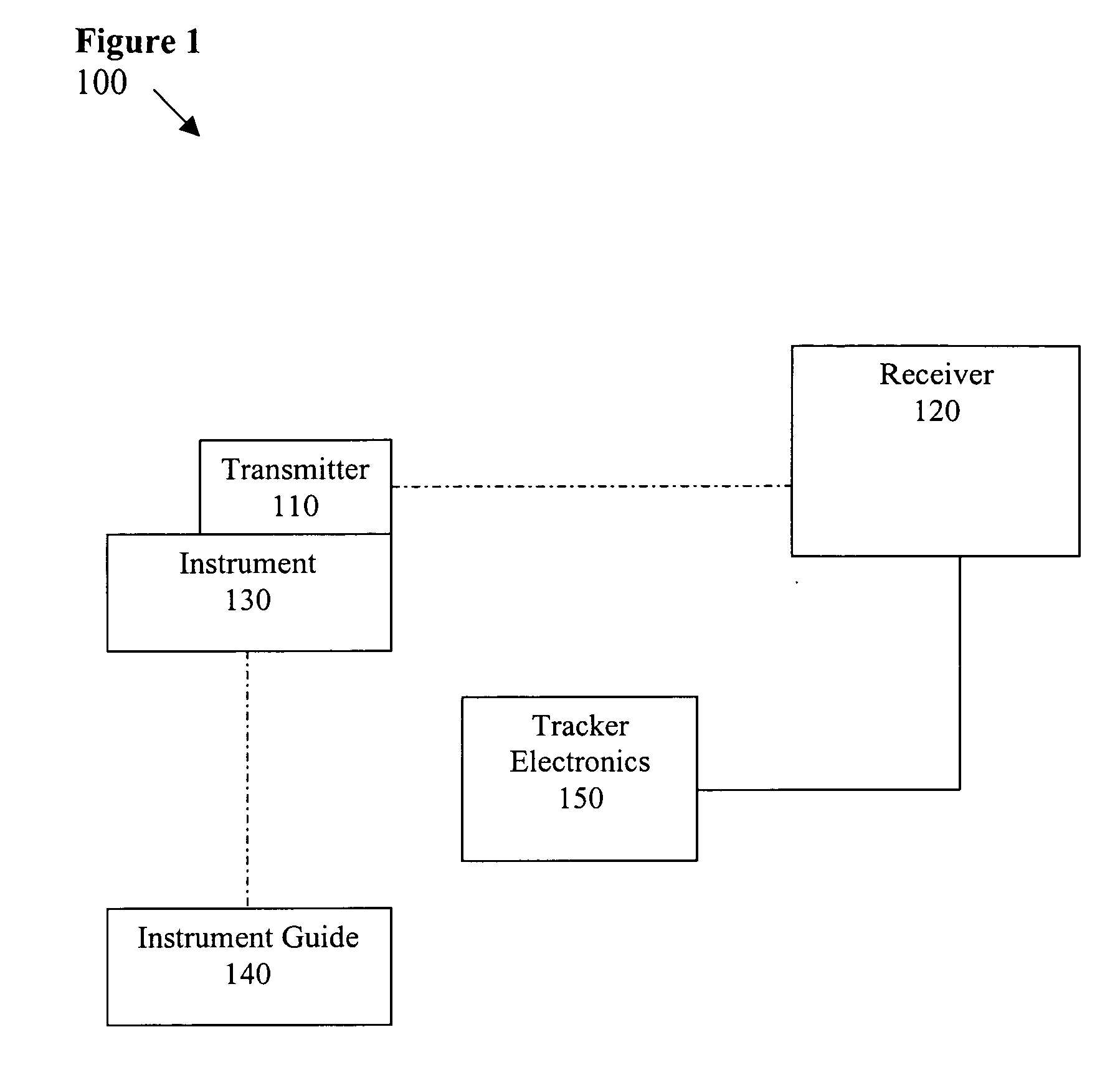
[0024]FIG. 1 illustrates an electromagnetic tracking system 100 used in accordance with an embodiment of the present invention. The tracking system 100 includes a transmitter 110, a receiver assembly 120, and a tracker electronics 150. The transmitter 110 may be a wired or wireless transmitter, for example. In an embodiment, the wireless transmitter 110 is positioned on an instrument 130. The receiver assembly 120 is located remotely from the instrument 130 and the transmitter 110. In an embodiment, an instrument guide 140 is used to control the instrument 130. The tracker electronics 150 may be integrated with the receiver assembly 120 or may be a separate module, for example. In an embod...


PUM


Abstract

Certain embodiments of the present invention provide a transformer-coupled guidewire system and method. Certain embodiments include a transmitter coil positioned in a distal end of a guidewire, a pickup coil positioned at a proximal end of the guidewire, and a first winding coiled apart from the guidewire. The guidewire is positioned with respect to the first winding such that the first winding is inductively coupled to the pickup coil to form a transformer providing power to the transmitter coil. The guidewire may include a catheter or a catheter may be positioned over the guidewire, for example. In an embodiment, the pickup coil serves as a secondary winding to form a transformer using the first winding and the pickup coil. The first winding may be coiled around a core, for example. The core may include an air gap longer than a length of the pickup coil, for example.

Description

RELATED APPLICATIONS [0001] [Not Applicable]FEDERALLY SPONSORED RESEARCH OR DEVELOPMENT [0002] [Not Applicable]MICROFICHE / COPYRIGHT REFERENCE [0003] [Not Applicable]BACKGROUND OF THE INVENTION [0004] The present invention generally relates to imaging and image-guided navigation. In particular, the present invention relates to a system and method for non-contact powering of a guidewire and / or catheter. [0005] Medical practitioners, such as doctors, surgeons, and other medical professionals, often rely upon technology when performing a medical procedure, such as image-guided surgery or examination. A tracking system may provide positioning information for the medical instrument with respect to the patient or a reference coordinate system, for example. A medical practitioner may refer to the tracking system to ascertain the position of the medical instrument when the instrument is not within the practitioner's line of sight. A tracking system may also aid in pre-surgical planning. [000...

Claims


Application Information

Patent Timeline
Patent Type & Authority Applications(United States)
IPC IPC(8): A61B5/05A61M31/00A61M25/00
CPCA61B2019/5251A61M25/01A61N1/37229A61M2025/0166A61M25/09A61B2034/2051
Inventor ANDERSON, PETER TRANEUSSCHIFF, JONATHAN DAVID
Owner GENERAL ELECTRIC CO
Why Eureka
Try Eureka