Wireless charging device

a wireless charging and charging device technology, applied in the direction of electric vehicles, transmission, transportation and packaging, etc., can solve the problems of user injury, increased energy loss, and power-providing devices cannot charge multiple power-receiving devices at the same time, so as to reduce electromagnetic radiation injury and enhance the charging efficiency of wireless charging devices

Inactive Publication Date: 2016-11-03
J TOUCH CORPORATION
View PDF2 Cites 46 Cited by
  • Summary
  • Abstract
  • Description
  • Claims
  • Application Information

AI Technical Summary

Benefits of technology

[0007]An object of the present invention provides a wireless charging device capable of automatically and wirelessly charging a power-receiving device when the power-receiving device is loaded into a main body of the wireless charging device. Moreover, the wireless charging device is capable of suppressing the divergence of the electromagnetic wave in order to reduce the electromagnetic radiation injury. Moreover, since the electromagnetic wave is converged to a charging zone to charge one or more power-receiving devices in a non-contact manner, the charging efficiency of the wireless charging device is enhanced.
[0008]Another object of the present invention provides a wireless charging device suitably used in a vehicle body. The wireless charging device is capable of emitting an electromagnetic wave with one or more frequencies so as to wirelessly charge one or more power-receiving devices at the same time or at different times. Moreover, the wireless charging device has an accommodation space for accommodating the one or more power-receiving devices. Consequently, the one or more power-receiving devices within the accommodation space can be wirelessly charged by the wireless charging device at the same time or at different times. Under this circumstance, the wireless charging application and convenience are enhanced.

Problems solved by technology

However, since the power-receiving device should be aligned with and attached on the power-providing device according to the magnetic induction technology, the power-providing device cannot charge plural power-receiving devices simultaneously.
Moreover, if the wireless charging task of the wireless charging device 11 is enabled when no power-receiving device 12 is placed in the charging zone, the energy loss increases.
Consequently, the user is possibly hurt by the electromagnetic wave (especially the high energy electromagnetic wave for high-watt power-receiving device), and the charging efficiency of the wireless charging device 11 is usually insufficient.
Moreover, while the vehicle is driven, the power-receiving device 12 may fall down because of the rocking condition of the vehicle body.
Under this circumstance, the power-receiving device 12 is possibly damaged.
Consequently, the user is possibly hurt by the electromagnetic wave, and the charging efficiency of the wireless charging device 11 is usually insufficient.
Under this circumstance, the components of the wireless charging devices and the components of the power-receiving devices are incompatible.
Under this circumstance, the applications of the wireless charging device are restricted.
Moreover, the wireless charging device is unable to wirelessly charge plural power-receiving devices which are designed according to different wireless charging technologies.

Method used


Image

  • Wireless charging device
  • Wireless charging device
  • Wireless charging device

Examples


Embodiment Construction

[0031]The present invention will now be described more specifically with reference to the following embodiments. It is to be noted that the following descriptions of preferred embodiments of this invention are presented herein for purpose of illustration and description only. It is not intended to be exhaustive or to be limited to the precise form disclosed.

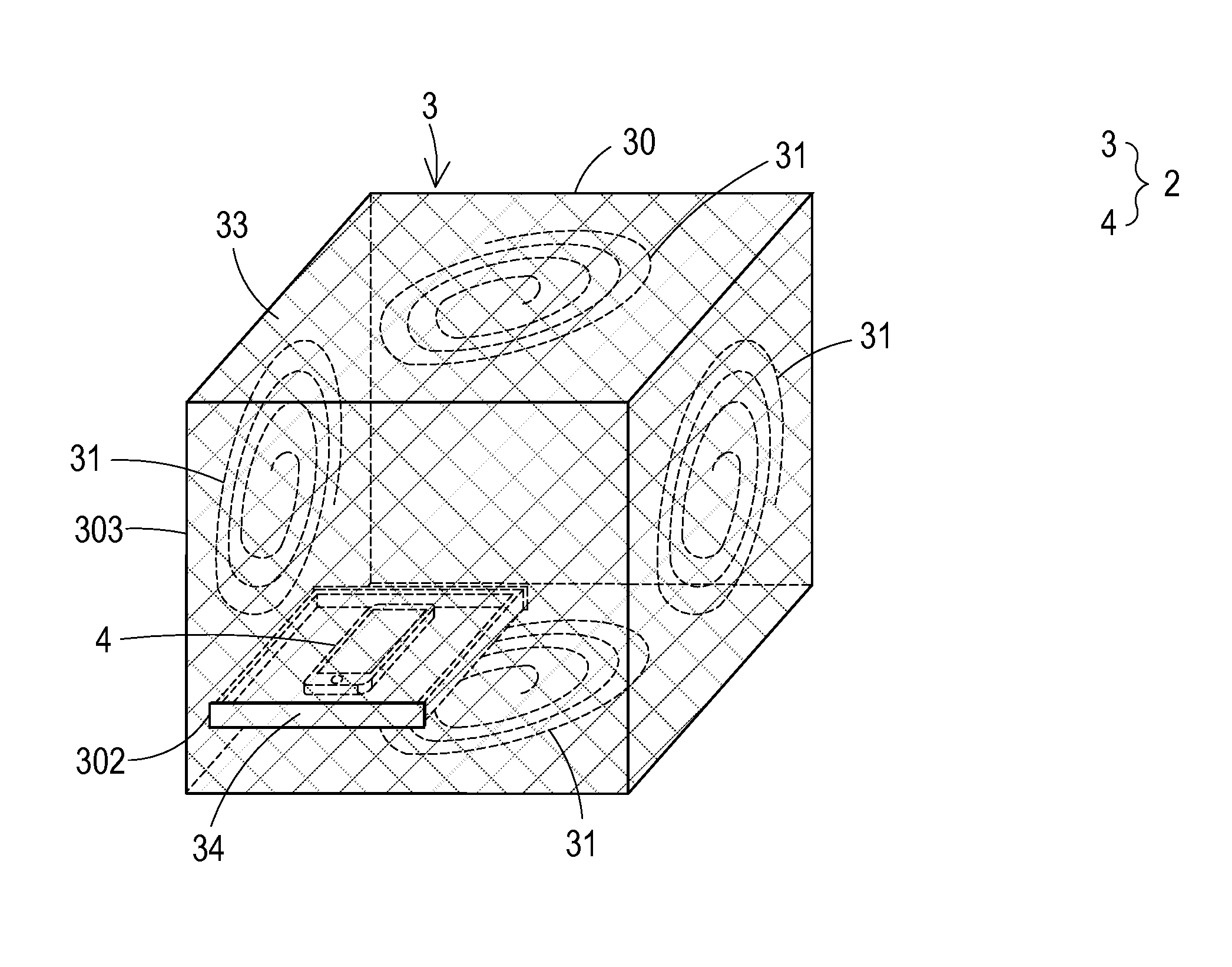
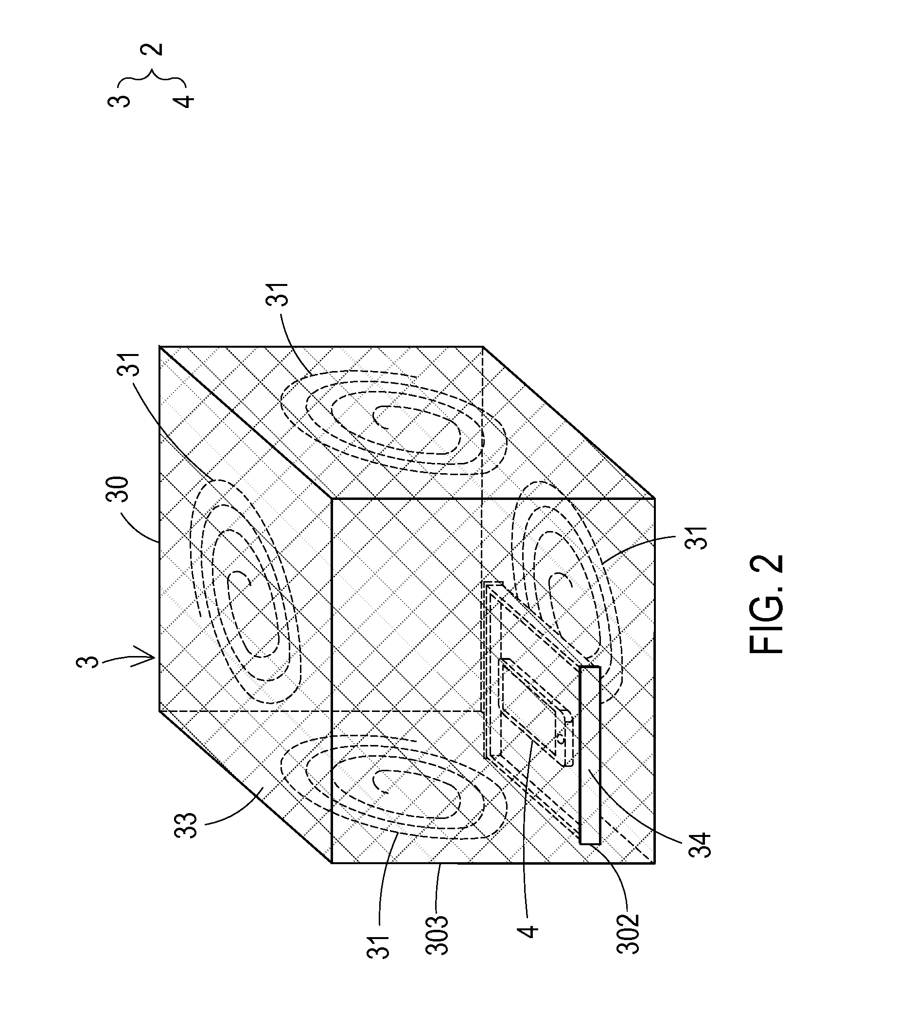
[0032]FIG. 2 is a schematic perspective view illustrating the appearance of a wireless charging device according to an embodiment of the present invention. FIG. 3 schematically illustrates the architecture of the wireless charging device of the wireless charging system according to the embodiment of the present invention. FIG. 4 schematically illustrates the architecture of the power-receiving device of the wireless charging system according to the embodiment of the present invention. FIG. 5A is a schematic cross-sectional view illustrating the wall part of the main body of the wireless charging device as shown in FIG. 3. FIG. 5B...


PUM


Abstract

A wireless charging device includes a main body, at least one transmitter coil assembly, at least one transmitter module, a shielding structure, a movable carrying unit and a controlling unit. Each transmitter coil assembly includes at least one antenna for emitting an electromagnetic wave with at least one specified frequency for wirelessly charging at least one power-receiving device. The movable carrying unit is disposed within an accommodation space of the main body for carrying the at least one power-receiving device. According to a result of judging whether the at least one power-receiving device is introduced into or removed from the accommodation space of the main body through the movable carrying unit, the at least one transmitter module is enabled or disabled by the controlling unit.

Description

FIELD OF THE INVENTION[0001]The present invention relates to a wireless charging device, and more particularly to a wireless charging device capable of automatically and wirelessly charging a power-receiving device when the power-receiving device is loaded into a main body thereof and capable of suppressing the divergence of the electromagnetic wave.BACKGROUND OF THE INVENTION[0002]Nowadays, various portable electronic devices such as mobile phones or tablet computers are widely used in our daily lives. For providing electric energy to the portable electronic device, a charging device is used to charge a built-in battery of the portable electronic device. Generally, the charging devices are classified into wired charging devices and wireless charging devices. Since the wireless charging device can be operated in various environments and not restricted by the power cable, the wired charging device is gradually replaced by the wireless charging device.[0003]The wireless charging opera...

Claims


Application Information

Patent Timeline
Patent Type & Authority Applications(United States)
IPC IPC(8): H02J7/02H02J7/04H02J7/00
CPCH02J7/025H02J7/04H02J7/0042H04B5/0037H04B5/0075H02J50/402H02J7/0044H02J50/12H02J50/70
Inventor YEH, YU-CHOUYEH, TSUNG-HERWU, CHEN-CHIYEH, CHUN-TINGHUANG, HSUEH-JUNGCHENG, BO-RUEIHU, CHIH-MINGTSUI, CHIU-CHENGLIN, HSIU-HUNG
Owner J TOUCH CORPORATION
Why Eureka
Try Eureka