Method and device for detecting a device in a wireless power transmission system

Active Publication Date: 2012-03-22
KONINKLIJKE PHILIPS ELECTRONICS NV
View PDF20 Cites 51 Cited by
  • Summary
  • Abstract
  • Description
  • Claims
  • Application Information

AI Technical Summary

Benefits of technology

[0006]It would be advantageous to provide a method and a

Problems solved by technology

Moreover, the proposed detection method works

Method used


Image

  • Method and device for detecting a device in a wireless power transmission system
  • Method and device for detecting a device in a wireless power transmission system
  • Method and device for detecting a device in a wireless power transmission system

Examples


Embodiment Construction

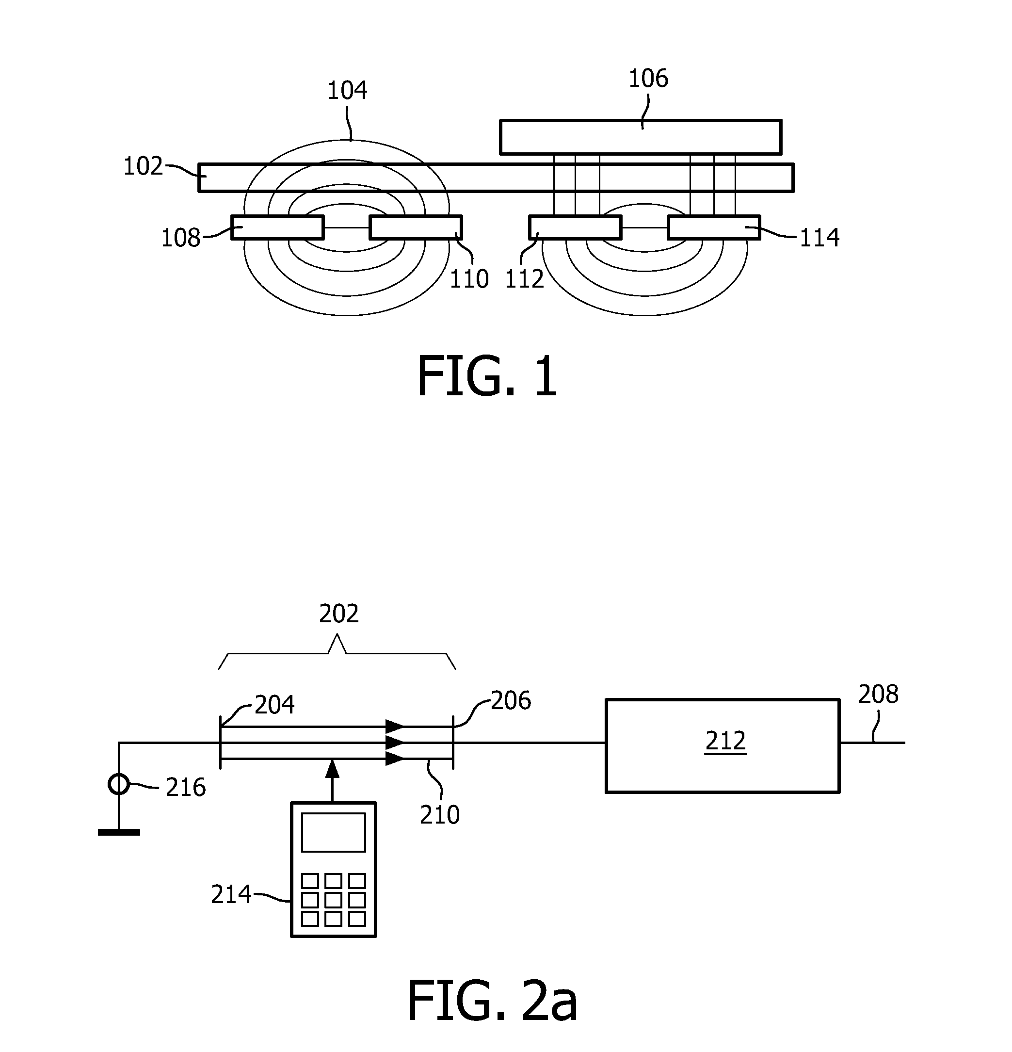
[0081]FIG. 1 depicts the principle of a method of detecting a device 106 that is placed on the surface 102 of the transmitter according to the present invention. Electrodes 108, 110, 112, 114 beneath the transmitter surface are used to detect devices 106 to be charged that are placed on the transmitter surface 102. The method is based on the fact that a device 106 that is placed on a surface 102 of a transmitter will change the capacitance between two electrodes 108, 110, 112, 114 located below the top surface 102 of a transmitter. The placement of such devices 106 on the transmitter surface 102 changes the value of the capacitance that exists between the different electrodes 108, 110, 112, 114. This results from the induced change in dielectric constant of part of the space between the two capacitor plates formed by the electrodes 108, 110, 112, 114, the dielectric distance of the two electrodes or a combination thereof. The change in capacitance is represented in FIG. 1 by the dif...


PUM


Abstract

A method of detecting a receiver (214) by a transmitter and a transmitter for detecting a receiver are provided. The transmitter is intended to transmit power inductively to the receiver (214). The transmitter comprising a first transmission coil as a first electrode (204) and a second electrode (206). The first electrode (204) and the second electrode (206) form a capacitor (202). The method comprises the steps of applying a voltage (216) to any one of the electrodes (204, 206) and detecting a capacitance change of the capacitor (202).

Description

FIELD OF THE INVENTION[0001]The invention relates to power transmission technology.BACKGROUND OF THE INVENTION[0002]To charge the batteries of battery-powered devices, such as cellular phones, PDAs, remote controls, notebooks etc., or directly power devices such as lamps or kitchen appliances, an inductive power system enabling a wireless power transfer can be applied. Inductive power systems for transferring power or charging mobile devices are, for example, known from WO 2008 / 050260. Such a system in general comprises a power transmitting device, hereafter called transmitter, comprising a plurality of transmitter coils which can individually be energized, thereby generating an alternating magnetic field. The inductive power system further comprises a power receiving device comprising a load requiring power. In order to receive power, the power receiving device is provided with a receiver coil, in which the alternating magnetic field, provided by the energized transmitter coils, in...

Claims


Application Information

Patent Timeline
IPC IPC(8): H01F38/14G01R27/26
CPCH02J7/025H04B5/0037H02J17/00H02J50/12H02J50/60H02J50/90H02J50/005G05F3/06H02J50/80
Inventor BOER, BART MICHIEL DEVAN WAGENINGEN, ANDRIESLOEF, CHRISTOPHWAFFENSCHMIDT, EBERHARDSEBOODT, LENNARTTREFFERS, MENNO ANNE
Owner KONINKLIJKE PHILIPS ELECTRONICS NV
Why Eureka
Try Eureka