
Micromachined gas and liquid concentration sensor and method of making the same

Active Publication Date: 2009-01-15
SIARGO SHANGHAI LTD
View PDF5 Cites 30 Cited by
  • Summary
  • Abstract
  • Description
  • Claims
  • Application Information

AI Technical Summary

Benefits of technology

[0008]It is therefore an object of the present invention to provide a process of a MEMS silicon concentration sensor applicable for concentration metrology of any fluid system of binary components with the advantages of the capability to synchronously measure flow rate of media if the said fluid system maintains a constant or variable flow conditions. The said concentration sensor shall also require a low power consumption that can be supplied by a battery. This object is reached by the independent claims.
[0011]In the present preferred embodiments, the heater thermistor is standing on a thermally isolated thin film membrane as the reference resistor is solely located on top of substrate to keep good thermal conductivity to the environment. Both thermistors are encapsulated with a 0.3˜0.5 micron thick dielectric film as passivation layer, which is also comprised in the suspended membrane. Above the dielectric film, a thin layer of fluorocarbon coating is deposited onto whole device to make the surface of device become hydrophobic and low surface energy. The thin hydrophobic fluorocarbon coating will significantly prevent alien particles or debris or liquid materials to stick on device surface which could degrade device operation. The cavity underneath the suspending membrane is fabricated by anisotropic bulk etching of the silicon substrate.

Problems solved by technology

On the other hand, the sensitivity may become inferior if the heating and sensing resistors are separated further.
Another drawback is that the invention can only limit to function in a static gas blend situation.
The other drawbacks of this invention are coming from the requirements of double sensors, which are more costly, and the complexity of sensors disposition.

Method used


Image

  • Micromachined gas and liquid concentration sensor and method of making the same
  • Micromachined gas and liquid concentration sensor and method of making the same
  • Micromachined gas and liquid concentration sensor and method of making the same

Examples


Embodiment Construction

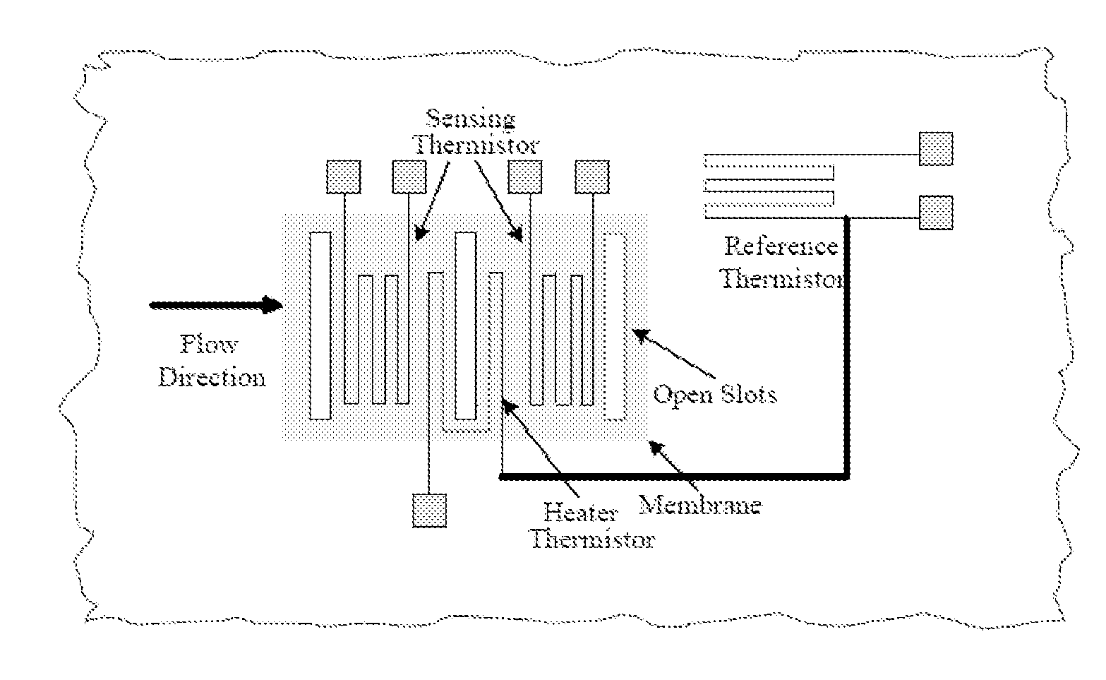
[0022]FIG. 2 illustrates a top view of preferred sensor topology. The reference thermistor is used to measure the ambient temperature. The ambient temperature signal will be feedback to a closed-loop heater thermistor control circuit. The control circuit is to keep the heater temperature constantly above the ambient temperature. The sensing thermistors besides the heater thermistor are worked as the flow speed sensing elements.

[0023]The working principle behind the fluid concentration measurement in a binary-component system is primarily based on anemometry and calorimetry. Since the heater thermistor is operating under constant temperature mode, there are two major features will influence the output signal: the fluid concentration and the fluid flow speed. In a static flow, the fluid flow speed contribution will be nullified, whereas in the dynamic flow, the output signal is contributed by both. Therefore the fluid flow speed must be measured separately and be differentiated from t...


PUM


Abstract

A device with micromachined (a.k.a. MEMS, Micro Electro Mechanical Systems) silicon sensor to measure gas or liquid concentration in a binary mixture formality is disclosed in the present invention. A process for fabricating the said MEMS silicon concentration sensor, which thereby can greatly reduce the sensor fabrication cost by a batch production, is revealed as well. This MEMS process can mass-produce the sensors on silicon substrate in the ways of small size, low power, and high reliability. In addition to the gas or liquid concentration measurement, the present invention further discloses that the said sensor can also readily measure gas or liquid mass flow rate while record the concentration data, which is not viable by other related working principle.

Description

BACKGROUND OF THE INVENTION[0001]1. Field of the Invention[0002]The present invention relates to a method and a device for measuring gas or liquid concentration in a binary mixture formality according to the preamble of the independent claims. The present invention also provides the methods and process for fabricating the device with micromachining or Micro Electro Mechanical Systems (MEMS) approach.[0003]2. Description of the Related Art[0004]Various gas or liquid concentration meters have been heretofore developed and commercially available on the market. The gas concentration sensors are broadly deployed in the fields such as oxygen, nitrogen, and other inert gas concentration detection. The liquid concentration sensors are applied on beverage, pharmaceutical, and chemical industries etc. The operation principles behind these commercial products are mainly based on the methods such as electrochemical reaction (H. Weyl and B. Wild, Measuring Device, U.S. Pat. No. 6,039,856; H. Die...

Claims


Application Information

Patent Timeline
IPC IPC(8): G01N25/00G01F1/68
CPCG01F1/6845G01N25/20G01F1/692
Inventor CHEN, CHIH-CHANGYAO, YAHONGWANG, GAOFENGHUANG, LIJI
Owner SIARGO SHANGHAI LTD
Learn More