

Compact optical transceiver module
- Summary
- Abstract
- Description
- Claims
- Application Information
AI Technical Summary
Benefits of technology
Problems solved by technology
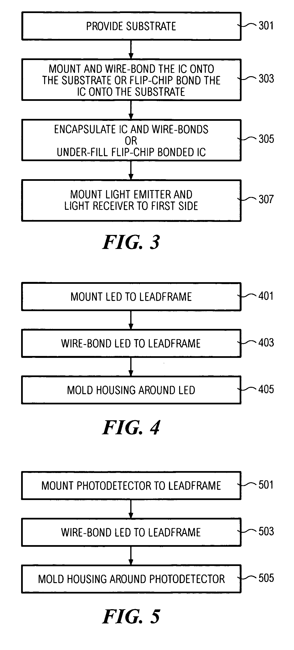
Method used
Image

Examples
Embodiment Construction
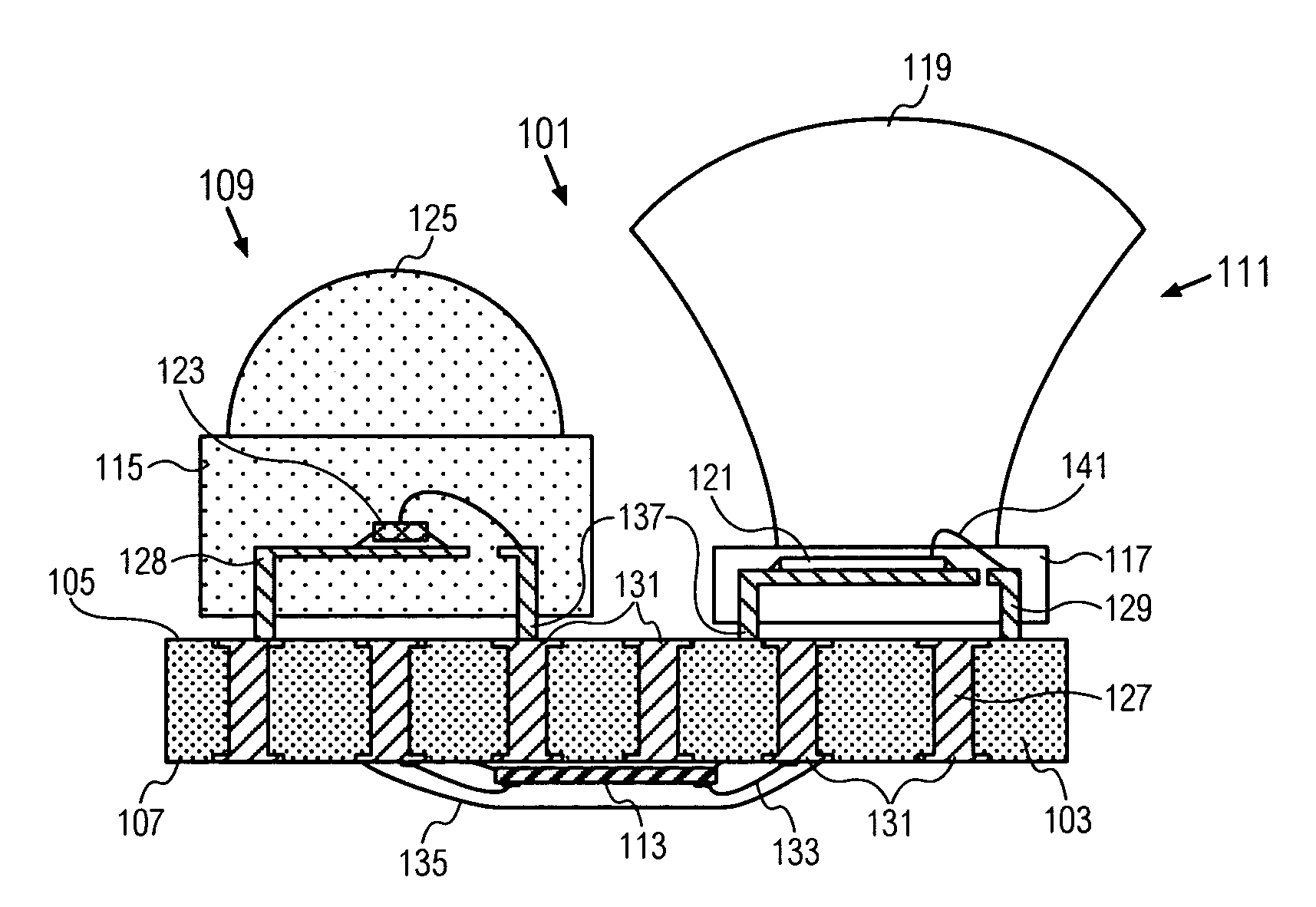
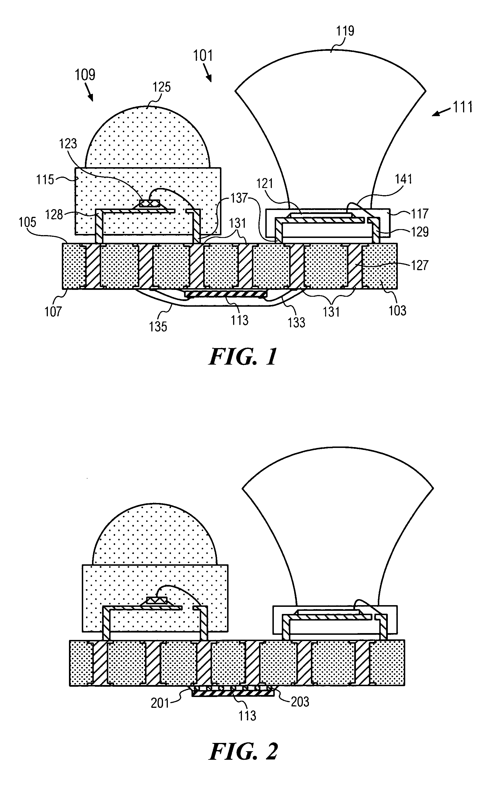
[0020]FIG. 1 shows an optical transceiver 101. A substrate 103 has a first side 105 and a second side 107. A light emitter 109 and a light receiver 111 are mounted to the first side 105. The light emitter 109 and light receiver 111 can be mounted to the first side 105 by means of leadframes 128, 129, respectively. Amplification circuits 113 are mounted to the second side 107 and are electrically connected to the light emitter 109 and the light receiver 111 through electrical terminals 127 passing through the substrate 103. The amplification circuits 113 drive the light emitter 109 to generate an output signal and also amplify the input signal received by the light receiver 111.
[0021] By mounting the light emitter 109 and light receiver 111 on the opposite side of the substrate 103 relative to the amplification circuits 113, the optical transceiver 101 has a smaller footprint than the transceiver of Rosenberg where the emitter, receiver and IC are all mounted on the same side of the...
PUM
 Abstract
Description
Claims
Application Information