Organometal complex and light-emitting element using the same

Active Publication Date: 2005-11-03
SEMICON ENERGY LAB CO LTD
View PDF1 Cites 32 Cited by
  • Summary
  • Abstract
  • Description
  • Claims
  • Application Information

AI Technical Summary

Benefits of technology

[0056] By implementing the present invention, a novel organometallic complex in which intersystem crossing to a triplet excited tends to occur can be obtained. In addition, a light-emitting element that is novel favorable heat resistance can be obtained by manufa

Problems solved by technology

In addition, such a compound can often emit phosphorescence.
However, many of the ligands have difficulty in be synthesized or have many steps required for synthesizing, which leads to price increases of materials themselves.
In these organometallic cimplexes, though it is often the case that iridium or platinum is used as a central metal to emit phosphorescence, these metals

Method used


Image

  • Organometal complex and light-emitting element using the same
  • Organometal complex and light-emitting element using the same
  • Organometal complex and light-emitting element using the same

Examples


embodiment 1

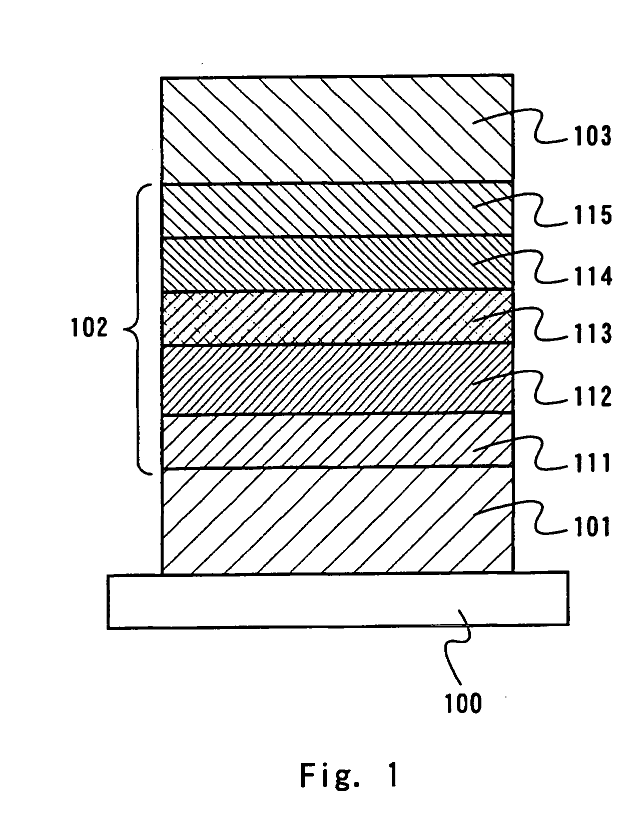
[0079] In Embodiment 1, the structure of a light-emitting element that has a light-emitting layer including the organometallic complex according to the present invention, and has a hole injection layer, a hole transporting layer, a hole blocking layer, and an electron transporting layer composed of low molecular weight materials will be described with reference to FIG. 1.

[0080] In FIG. 1, the light-emitting element according to the present invention has a structure in which a first electrode 101 is formed on a substrate 100, a layer 102 including a luminescent material is formed on the first electrode 101, and a second electrode 103 is formed thereon.

[0081] As a material to be used for the substrate 100 here, a material that is used for a conventional light-emitting element may be used. For example, glass, quartz, transparent plastic, and a flexible substrate can be used.

[0082] In addition, the first electrode 101 and the second electrode 103 in Embodiment mode 1 function as an a...

embodiment 2

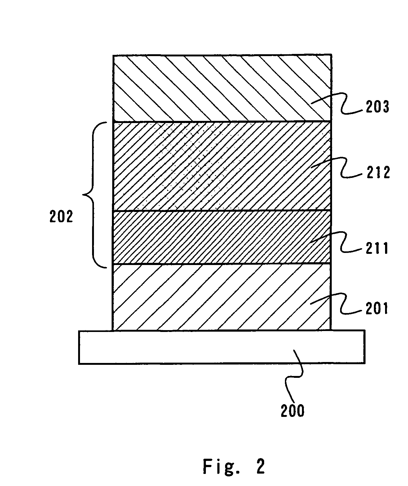
[0096] In Embodiment 2, the structure of a light-emitting element that has a light-emitting layer including an organometallic complex according to the present invention and a hole injecting layer compsed of a polymer material, which are formed by a wet process, will described with reference to FIG. 2.

[0097] It is noted that a substrate 201, a first electrode 201, and a second electorode 203 can be formed by using the same materials in the same way as in Embodiment 1. Terefore, descriptions thereof are omitted.

[0098] Further, a layer 202 including a luminescent marterial is formed by stacking a plurarity of layers, in Embodiment 2, by stacking a hole injecting layer 211 and a light-emitting layer 212.

[0099] As a hole injecting material forming the hole injecting layer 211, polyethylenedioxythiophene (abbreviation: PEDOT) doped with polystyrene sulfonate (abbreviation: PSS), polyaniline, and polyvinyl carbazole (abbreviation: PVK) can be used.

[0100] The light-emitting layer 212 in...

embodiment 3

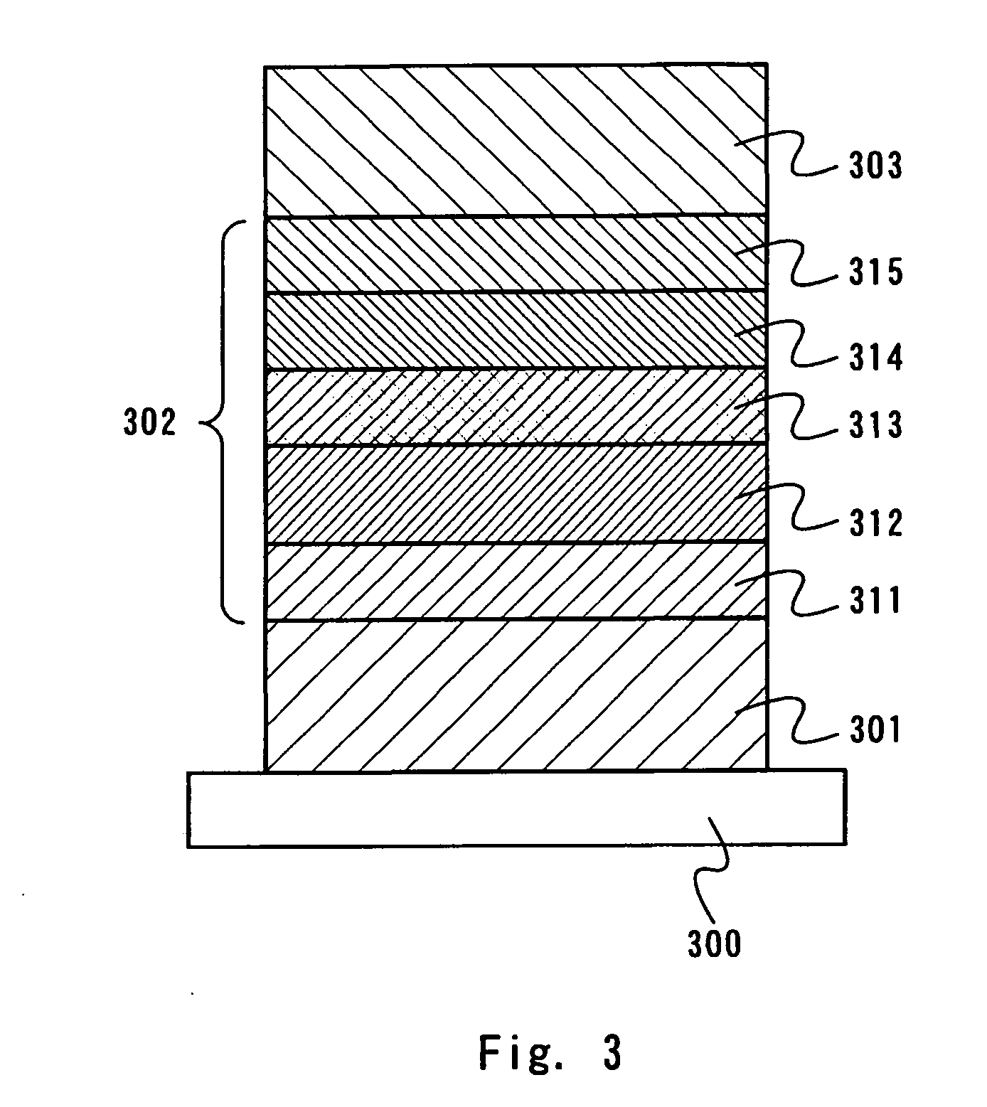
[0102] In Embodiment 3, the structure of a light-emitting element that has a light-emitting layer including two kinds of materials which are an organometallic complex according to the present invention and a fluorescent compound, and a hole injecting layer, a hole transporting layer, a hole blocking layer, and an electron transporting layer which are composed of low molecular weight materials will be described with reference to FIG. 3. In FIG. 3, there is a layer 302 including a luminescent material between a first electrode 301 and a second electorode 303. The layer 302 including the luminescent material is formed by stacking a hole injecting layer 311, a hole transporting layer 312, a light-emitting layer 313, a hole blocking layer 314, and an electron transporting layer 315.

[0103] It is to be noted that a substrate 300, the first electrode 301, the second electrode 303, the hole injecting layer 311, the hole transporting layer 312, the hole blocking layer 314, and the electron t...


PUM


Abstract

An organometallic complex according to the present invention comprises a structure represented by the following general formula (1). In the formula, R1 to R5 are any one selected from the group consisting of hydrogen, a halogen element, an acyl group, an alkyl group, an alkoxyl group, an aryl group, a cyano group, and a heterocyclic group, Ar is an aryl group having an electron-withdrawing group or a heterocyclic group having electron-drawing group, and M is an element of Group 9 or an element of Group 10.

Description

TECHINICAL FIELD [0001] The present invention relates to a novel organometallic complex, and more particularly relates to an organometallic complex that is capable of converting a triplet excited state into luminescence. Further, the present invention relates to a light-emitting element that has an anode, a cathode, and a layer including an organic compound (hereinafter, referred to as “a layer including a luminescent material”) from which luminescence can be obtained by applying an electric field. BACKGROUND ART [0002] An organic compound (organic molecule) gets to have energy (excited state) by absorbing light. Through the excited state, various reactions (photochemical reactions) and luminescence may be generated, and are used for various applications. [0003] As an example of photochemical reactions, there is a reaction of a singlet oxygen with an unsaturated organic molecular (oxygenation) (for example, refer to Non-Patent Reference 1). Oxygen in a singlet state (singlet oxygen)...

Claims


Application Information

Patent Timeline
IPC IPC(8): C07F15/00C09K11/06H01L51/00H01L51/50H05B33/14
CPCC07F15/0033C09K11/06C09K2211/1044H05B33/14H01L51/0085H01L51/5016C09K2211/185H10K85/342H10K50/11H10K2101/10H10K85/346C07F17/02C09K2211/1025
Inventor INOUE, HIDEKOSEO, SATOSHISHITAGAKI, SATOKOABE, HIROKO
Owner SEMICON ENERGY LAB CO LTD
Why Eureka
Try Eureka