Wireless power transmission system and method controlled via digital messages

a power transmission system and digital message technology, applied in battery data exchange, electric vehicles, transportation and packaging, etc., can solve the problems of increasing energy costs, affecting the efficiency of power transmission, so as to achieve the effect of increasing the transfer power

Inactive Publication Date: 2016-11-10
POWERMAT TECHNOLOGIES
View PDF1 Cites 54 Cited by
  • Summary
  • Abstract
  • Description
  • Claims
  • Application Information

AI Technical Summary

Benefits of technology

[0162]Where appropriate, the step of executing instructions encoded in control signals included in said least one message communication, comprises increasing transfer power wherein said at least one message communication includes PMA_Dec signal

Problems solved by technology

On a global scale, there is increasing concern that the emission of greenhouse gases such as carbon dioxide from the burning of fossil fuels may precipitate global warming.
Moreover, energy resources are limited.
The scarcity of global energy resources alongside geopolitical factors drives the cost of energy upwards.
Energy losses in electrical energy transmission are chiefly due to the incidental heating of current carrying wires.
In many cases this is unavoidable, as current carrying wires are essential for the powering of electrical devices and current carrying wires have resistance.
In other cases the energy losses are unnecessary.
For example, electrical devices are often left running unnecessarily and energy used to power devices which are not being used is truly wasted.
Power losses due to the heating of a cable increase according to the square of the current it carries so energy losses from the cable may increase parabolically.
Furthermore, in the absence of effective energy management, if too ma

Method used


Image

  • Wireless power transmission system and method controlled via digital messages
  • Wireless power transmission system and method controlled via digital messages
  • Wireless power transmission system and method controlled via digital messages

Examples


Embodiment Construction

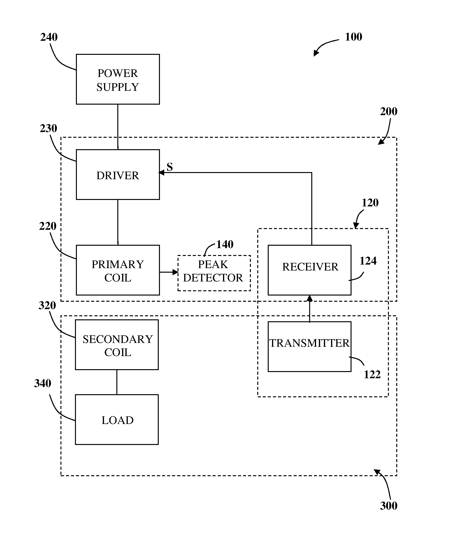
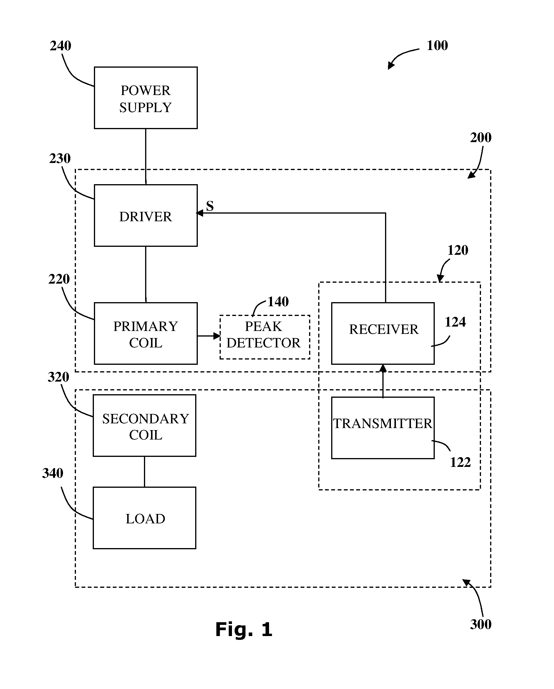
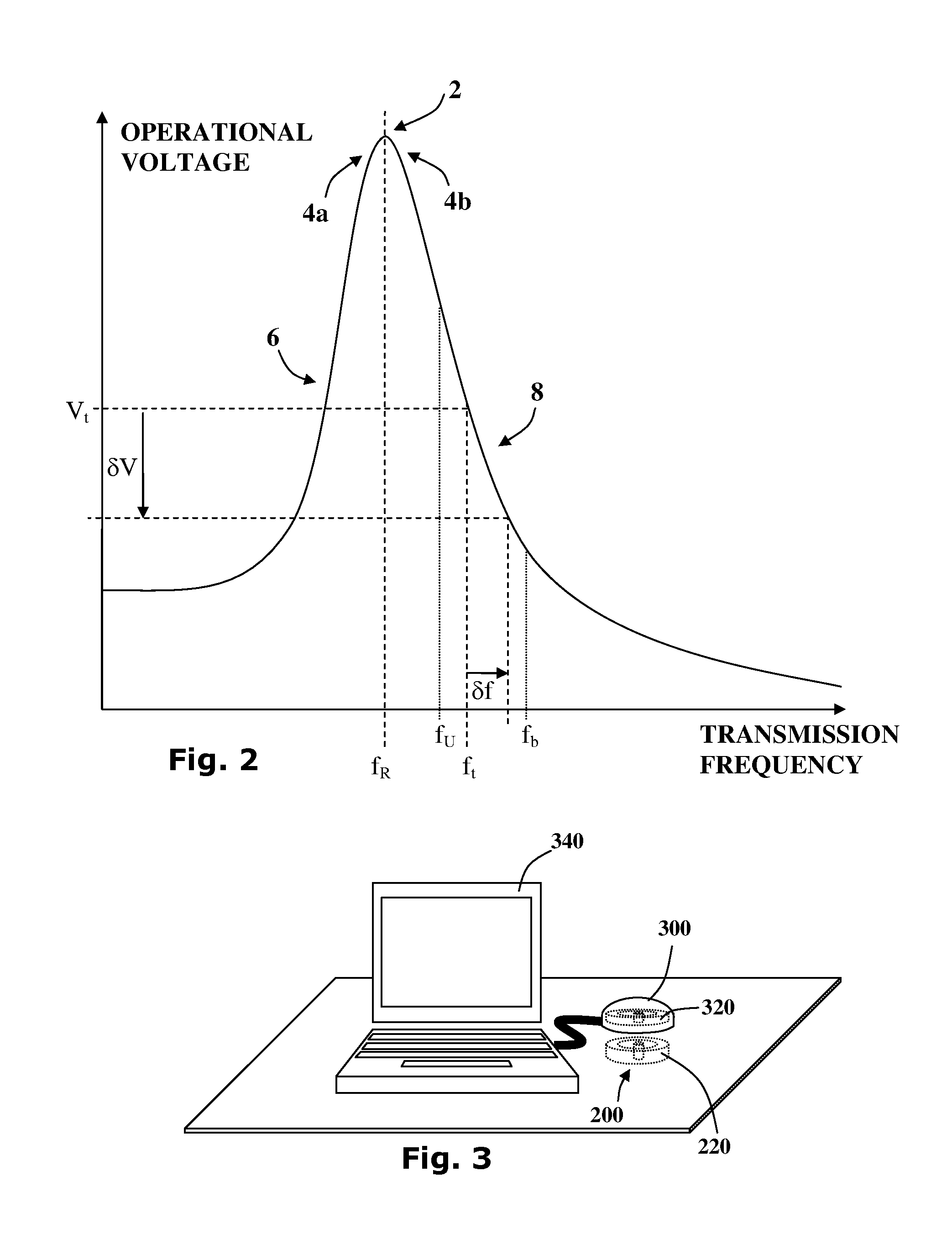
[0217]Aspects of the present invention relate to providing devices, systems and methods for energy efficient wireless power transfer. In particular, the disclosure relates to incorporating extended signaling supporting multi-directional communication to enable data transfer, higher power levels over extended range and improved foreign object detection (FOD) functionality.

[0218]It is noted that the extended signaling may also provide ability to transfer relatively low quantities of data from a power receiver coil connectable to a load, to a power transmitter coil.

[0219]It is further noted that the protocol of transferring data, from a power receiver coil to a power transmitter coil and vice versa, may be used for in band communication utilizing the medium used to transfer PMA signals or for out of band (OOB) communication channels like Bluetooth Low Energy (BLE), WiFi, audio communication, ultrasonic communication and the like.

[0220]It is noted that that the extended protocol allows ...


PUM


Abstract

The disclosure relates to systems and methods for controlling a wireless power transfer system based upon Inductive Charging Technology using frequency based signaling communication protocol, operable to function in modes of Standby, Digital Ping, Identification, Power Transfer and End of Charge (EOC). The power transfer system comprising at least one wireless power outlet associated with a wireless power transmitter coil and at least one electrical device associated with a wireless power receiver coil, where the wireless power receiver coil is in multi-directional communication with the wireless power transmission of a message transmitter coil. The amount of power transferred is controlled by feedback communication between the receiver and the transmitter configured to increase or NO decrease power. More specifically, the present disclosure supports wireless power transfer incorporating transmission opportunity extended signaling supporting uni-directional and bi-directional communication enabling data transfer over extended range, higher power levels of power transfer and improved foreign object detection functionality.

Description

FIELD OF THE INVENTION[0001]The present invention is directed to providing energy efficient inductive power transfer. More specifically, the present invention relates to wireless power transfer systems and methods incorporating extended signaling supporting multi-directional communication to enable data transfer over extended range, higher power levels and improved foreign object detection functionality.BACKGROUND OF THE INVENTION[0002]The efficient use of available energy is of great importance for a number of reasons. On a global scale, there is increasing concern that the emission of greenhouse gases such as carbon dioxide from the burning of fossil fuels may precipitate global warming. Moreover, energy resources are limited. The scarcity of global energy resources alongside geopolitical factors drives the cost of energy upwards. Thus efficient use of energy is an ever more important budget consideration for the energy consumer.[0003]Energy losses in electrical energy transmissio...

Claims


Application Information

Patent Timeline
IPC IPC(8): H02J50/12H02J7/02H02J50/90H02J50/80H02J50/20
CPCH02J50/12H02J50/80H02J7/025H02J50/90H02J50/20H02J7/00045H02J50/60
Inventor MACH, ELIESERMOSHKOVICH, OZKOREN, YUVALRAVEH, GUYSHERMAN, ITAYGREENWALD, OOLAROFE, ARIKPODKAMIEN, IAN
Owner POWERMAT TECHNOLOGIES
Why Eureka
Try Eureka