Cable temperature rise test method considering axial heat transfer of cable joint

A technology of cable joints and axial heat transfer, applied in the direction of measuring electricity, measuring electrical variables, instruments, etc., can solve the problems of inaccurate cable temperature rise test values, cost waste, etc., and achieve the effect of wide application range and cost reduction

Pending Publication Date: 2022-06-24
GUANGZHOU POWER SUPPLY BUREAU GUANGDONG POWER GRID CO LTD
View PDF0 Cites 0 Cited by
  • Summary
  • Abstract
  • Description
  • Claims
  • Application Information

AI Technical Summary

Problems solved by technology

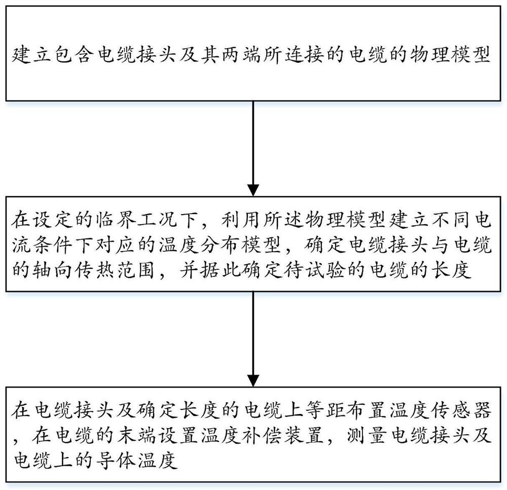
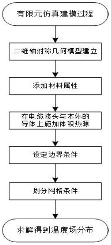
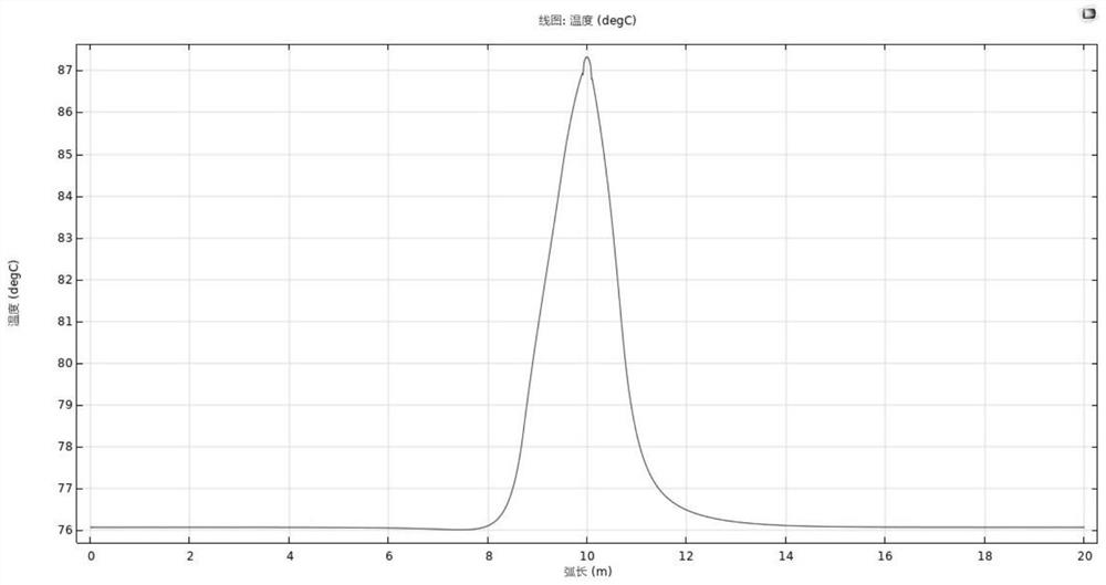
[0004] The purpose of the present invention is to provide a cable temperature rise test method considering the axial heat transfer of the cable joint to solve the problem of inaccurate cable temperature rise test values ​​and cost waste due to the axial heat transfer of the cable joint in the prior art. Methods The temperature field model of the cable joint and the main body was constructed through finite element simulation, and the length of the experimental cable main body was determined; then, a high-current temperature rise experimental loop was built according to the determined cable length, and temperature sensors were arranged equidistantly on the conductors of the cable joint and the main body , to monitor the conductor temperature of the cable joint in real time

Method used


Image

  • Cable temperature rise test method considering axial heat transfer of cable joint
  • Cable temperature rise test method considering axial heat transfer of cable joint
  • Cable temperature rise test method considering axial heat transfer of cable joint

Examples


Embodiment

[0040] It should be noted that the terms "first", "second" and the like in the description and claims of the present invention and the above drawings are used to distinguish similar objects, and are not necessarily used to describe a specific sequence or sequence. It is to be understood that the data so used may be interchanged under appropriate circumstances such that the embodiments of the invention described herein can be practiced in sequences other than those illustrated or described herein. In addition, the terms "comprising" and "having" and any variations thereof in the embodiments of the present invention are intended to cover non-exclusive inclusion, for example, a process, method, system, product or device comprising a series of steps or units is not necessarily limited to Those steps or elements that are expressly listed may instead include other steps or elements that are not expressly listed or are inherent to the process, method, product or apparatus.

[0041] I...


PUM


Abstract

The invention discloses a cable temperature rise test method considering axial heat transfer of a cable joint, and relates to the technical field of research on heat transfer and temperature rise characteristics of high-voltage cable joints, and the method comprises the steps: building a physical model comprising the cable joint and cables connected with the two ends of the cable joint; under a set critical working condition, establishing corresponding temperature distribution models under different current conditions by using the physical model, determining an axial heat transfer range of a cable joint and the cable, and determining the length of the cable to be tested according to the axial heat transfer range; temperature sensors are arranged on the cable joint and the cable with the determined length at equal intervals, and a temperature compensation device is arranged at the tail end of the cable to measure the temperature of the cable joint and the conductor on the cable. The axial heat transfer problem of the cable joint and the experiment equipment cost problem are considered at the same time, the cable line is used as short as possible under the condition that the influence of the axial heat transfer of the joint on the temperature rise of the cable body is eliminated, and the experiment platform cost is reduced.

Description

technical field [0001] The invention relates to the technical field of research on heat transfer and temperature rise characteristics of high-voltage cable joints, and specifically designs a cable temperature rise test method considering the axial heat transfer of the cable joint. Background technique [0002] With the continuous increase of national electric energy demand, the operating load of cable lines continues to increase. Long-distance cable lines need to be connected by intermediate cable joints. In high-voltage cable lines, the requirements for insulation are higher, which makes the volume of the joint insulation larger. Such a structural design will inevitably increase the heat transfer path of the intermediate cable joint, thereby increasing the Conductor temperature, resulting in overheating operation, and in severe cases, may lead to joint fire, explosion and other accidents. [0003] The radial thermal resistance of the cable body and the cable joint is analy...

Claims


Application Information

Patent Timeline
Patent Type & Authority Applications(China)
IPC IPC(8): G01R31/00
CPCG01R31/00
Inventor 苏俊亮张珏肖健健单鲁平慕容啟华徐研蚁暄潮马世禄顾侃全万霖
Owner GUANGZHOU POWER SUPPLY BUREAU GUANGDONG POWER GRID CO LTD
Why Eureka
Try Eureka