

Multi-purpose vehicle-mounted electronic product charger
A technology for in-vehicle electronics and chargers, applied in current collectors, battery circuit devices, and cleaning methods using tools, etc., can solve the problems of dust stuck on the push plate, resilience, card sag, difficult to take out and use, etc.
- Summary
- Abstract
- Description
- Claims
- Application Information
AI Technical Summary
Problems solved by technology
Method used
Image

Examples
Embodiment 1
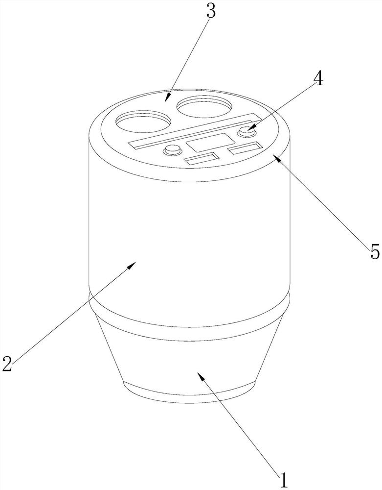
[0030] as attached figure 1 to the attached Image 6 shown:
[0031] The present invention provides a multi-purpose vehicle-mounted electronic product charger. Its structure includes a base 1, a storage box 2, a top cover 3, a control board 4, and a snap ring 5. The upper end of the storage box 2 is riveted and connected to the lower end of the snap ring 5 , the lower end of the top cover 3 is embedded and fixed to the upper end of the snap ring 5 , and the control board 4 and the top cover 3 are integrated structures.
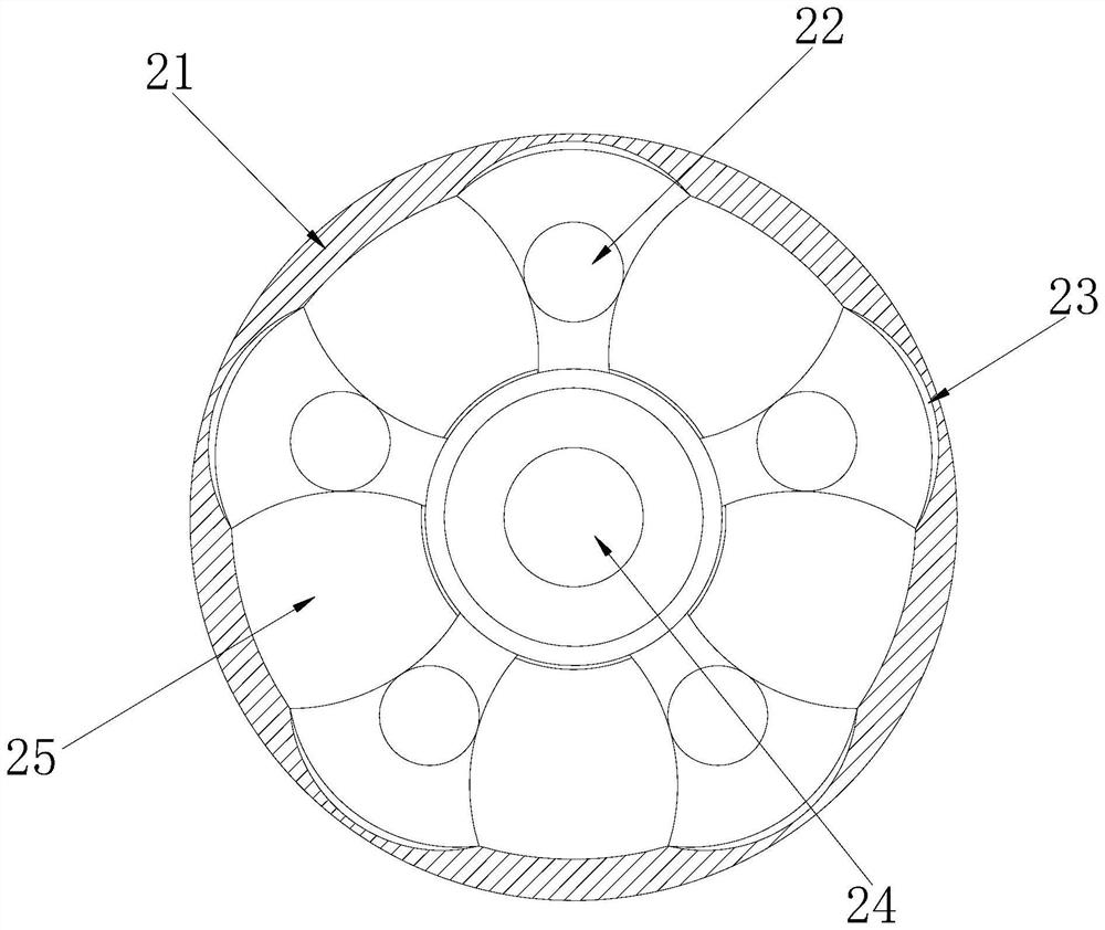
[0032] The storage box 2 is provided with a fixing ring 21, a pushing and removing device 22, a slideway 23, a vibrating device 24, and a top plate 25. The inner side of the fixing ring 21 is connected with the outer side of the slideway 23, and the pushing and removing device The outer side of 32 is engaged with the inner side of the slideway 33, the outer side of the vibration device 24 is movably engaged with the inner side of the pushing and removing dev...
Embodiment 2
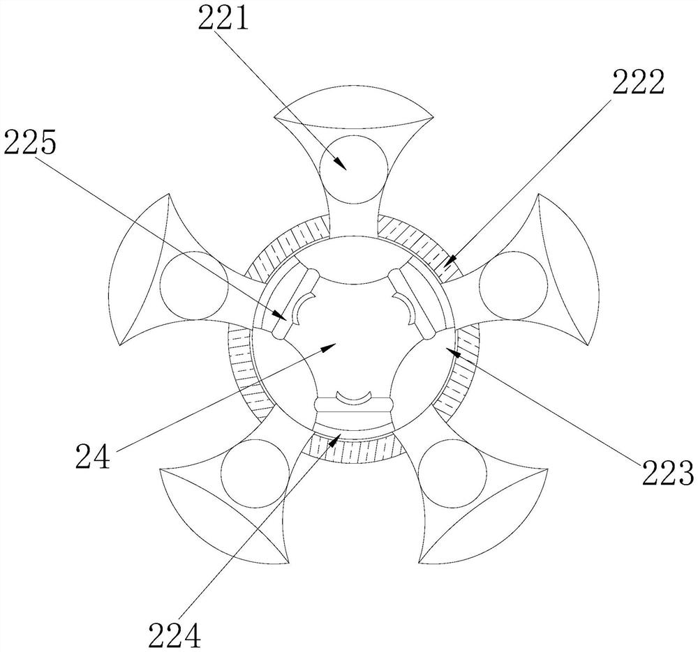
[0040] as attached Figure 7 to the attached Figure 9 shown:
[0041] The present invention provides a multi-purpose vehicle charger for electronic products. The vibration device 24 is provided with a vibration plate 241, a top column 242, a spring column 243, a sliding port 244, and a collar 245. The rear end of the vibration plate 241 is connected to the The front end of the spring column 243 is connected, the inner side of the top column 242 is fixedly connected to the outer side of the vibration plate 241, the rear end of the spring column 243 is embedded and fixedly connected to the front end of the collar 245, and the sliding port 244 is arranged on the inner side of the collar 245 to slide In cooperation, the outer side of the top post 242 is engaged with the inner side of the sliding port 244, the outer side of the collar 245 is engaged with the inner side of the ejector 22, and the outer side of the collar 245 is provided with ten notches, so that the ejector 22 can...
PUM
 Abstract
Description
Claims
Application Information