Multifunctional double-gun direct current charging pile and use method thereof
A technology of DC charging piles and charging piles, applied in charging stations, electric vehicle charging technology, electric vehicles, etc., can solve the problems of large footprint, single structure of charging piles, and few functions
- Summary
- Abstract
- Description
- Claims
- Application Information
AI Technical Summary
Problems solved by technology
Method used
Image
Examples
Embodiment 1
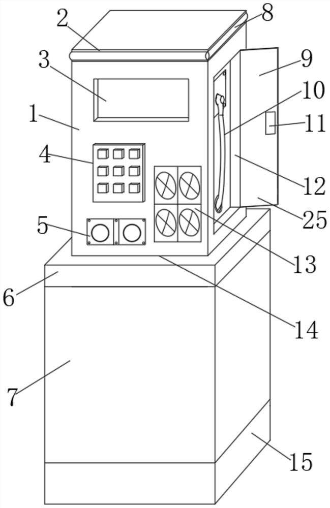
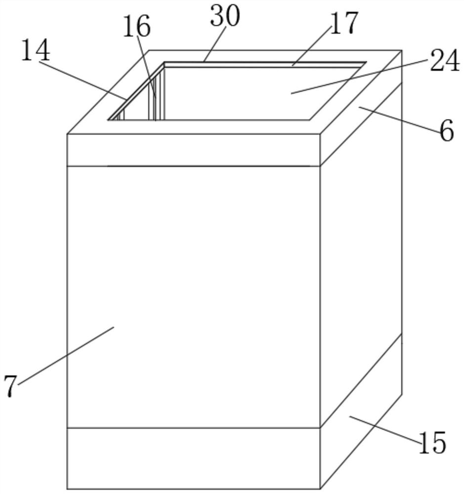
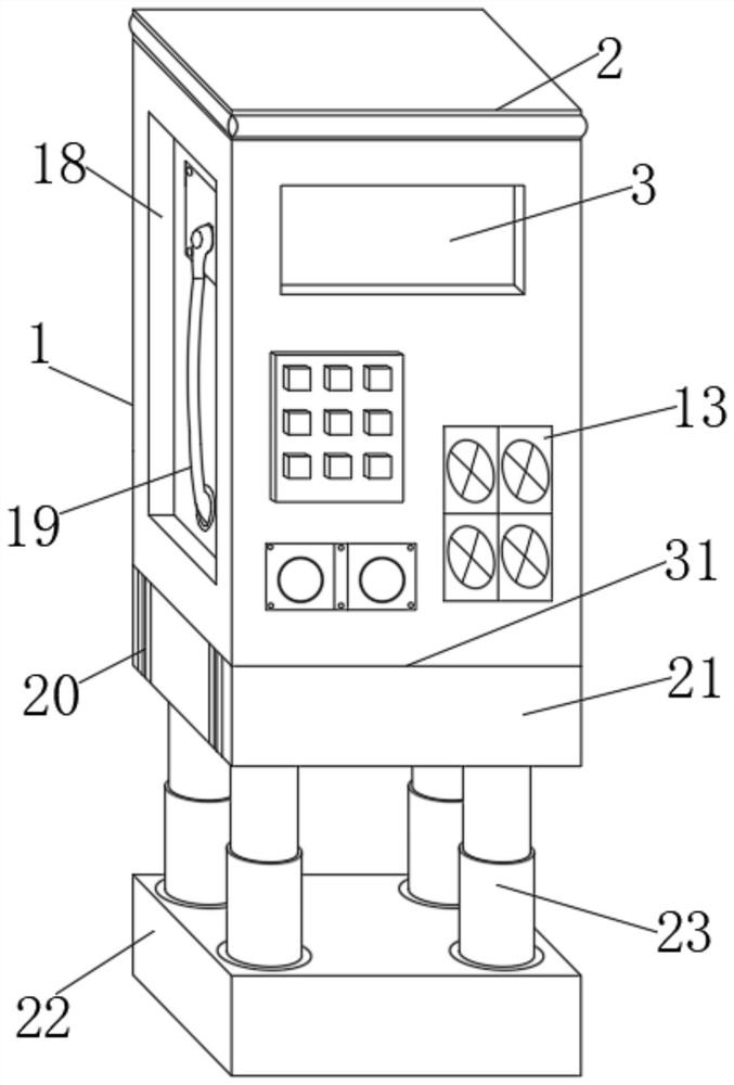
[0031] like Figure 1-6 As shown, a multi-functional dual-gun DC charging pile includes a charging pile main body 1 and a pre-embedded box 7. A sliding seat 21 is positioned and installed at the bottom of the charging pile main body 1, and a sealing seat 6 is installed at the upper end of the pre-embedded box 7. A base 15 is installed on the bottom of the embedded box 7, a pre-embedded groove 14 is opened on the inner side of the embedded box 7, the sliding seat 21 is located at the inner side of the embedded groove 14, and the front end of the charging pile main body 1 is provided with a display 3, a control panel 4, A mounting bracket 31 is installed between the fire extinguishing mechanism 5 , the fan cooling mechanism 13 , and the charging pile main body 1 and the sliding seat 21 .
[0032] As a preferred technical solution of the present application, a No. 1 charging box 12 is provided on one side of the main body 1 of the charging pile, a No. 1 charging gun 10 is installed...
Embodiment 2
[0037] On the basis of Example 1, as Figure 1-6 As shown, a multi-functional dual-gun DC charging pile includes a charging pile main body 1 and a pre-embedded box 7. A sliding seat 21 is positioned and installed at the bottom of the charging pile main body 1, and a sealing seat 6 is installed at the upper end of the pre-embedded box 7. A base 15 is installed on the bottom of the embedded box 7, a pre-embedded groove 14 is opened on the inner side of the embedded box 7, the sliding seat 21 is located at the inner side of the embedded groove 14, and the front end of the charging pile main body 1 is provided with a display 3, a control panel 4, A mounting bracket 31 is installed between the fire extinguishing mechanism 5 , the fan cooling mechanism 13 , and the charging pile main body 1 and the sliding seat 21 .
[0038] As a preferred technical solution of the present application, a support seat 22 is positioned and installed on the inner side of the base 15 , a drive cylinder ...
Embodiment 3
[0041] On the basis of Embodiment 1 and Embodiment 2, as Figure 1-6 As shown in the figure, a method of using a multi-functional dual-gun DC charging pile includes the following steps:
[0042] S1: The pre-embedded box 7 is pre-buried in the underground position. The pre-embedded box 7 is integrally formed with the sealing seat 6 and the base 15, and has waterproof and rust-removing performance. A sliding seat 21 is installed, the bottom of the sliding seat 21 is connected with the support seat 22 inside the base 15 through the lifter 23, and the charging pile main body 1 is driven to lift and lower inside the embedded box 7 by the position of the lifter 23;
[0043] S2: The maximum lifting height of the charging pile main body 1 is the position where the sliding seat 21 reaches the top opening of the embedded groove 14 and is sealed with the sealing protective pad 17. When the charging pile main body 1 is lowered to the bottom, the sliding seat 21 and the supporting seat 22 ...
PUM
 Abstract
Description
Claims
Application Information
 - R&D
- Intellectual Property
- Life Sciences
- Materials
- Tech Scout
- Unparalleled Data Quality
- Higher Quality Content
- 60% Fewer Hallucinations
Browse by: Latest US Patents, China's latest patents, Technical Efficacy Thesaurus, Application Domain, Technology Topic, Popular Technical Reports.
© 2025 PatSnap. All rights reserved.Legal|Privacy policy|Modern Slavery Act Transparency Statement|Sitemap|About US| Contact US: help@patsnap.com


