
Ship drag reduction system and drag reduction method thereof

A ship and bow technology, applied in the ship drag reduction system and its drag reduction field, can solve the problems that the reverse jet drag reduction technology has not attracted widespread attention, and the drag reduction effect has been discounted, so as to eliminate the singleness, improve the high pressure area, The effect of improving drag reduction efficiency

Inactive Publication Date: 2022-06-28
JIANGSU UNIV OF SCI & TECH
View PDF0 Cites 0 Cited by
  • Summary
  • Abstract
  • Description
  • Claims
  • Application Information

AI Technical Summary

Problems solved by technology

[0003] At present, most of the drag reduction forms envisioned for ships use a single air bubble drag reduction. Due to the complex shape of the ship's bottom, the bubbles float up and escape seriously, the drag reduction effect is greatly reduced, and the reverse jet drag reduction technology has not attracted widespread attention.

Method used


Image

  • Ship drag reduction system and drag reduction method thereof
  • Ship drag reduction system and drag reduction method thereof
  • Ship drag reduction system and drag reduction method thereof

Examples


Embodiment Construction

[0023] The present invention will be further clarified below in conjunction with the accompanying drawings and specific embodiments. It should be understood that these embodiments are only used to illustrate the present invention and not to limit the scope of the present invention.

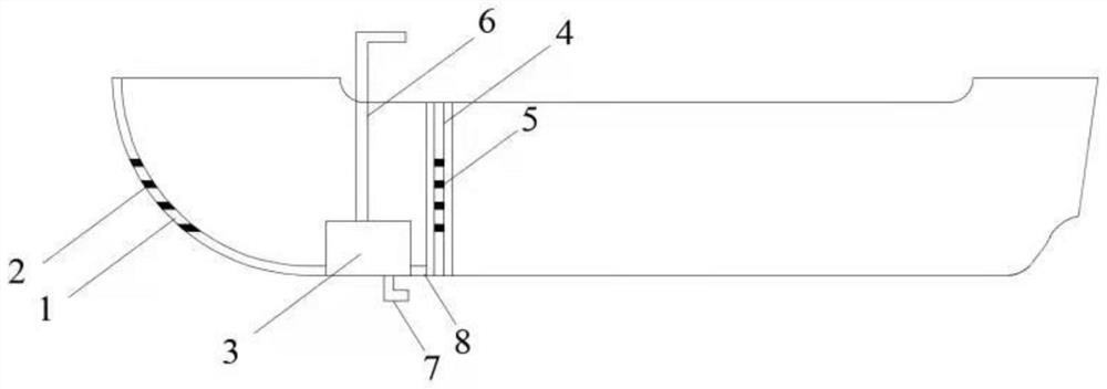
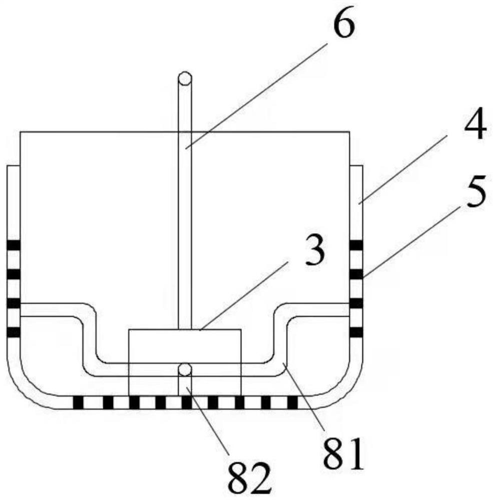
[0024] A ship drag reduction system, such as Figures 1 to 4 As shown, it includes an upstream liquid spray device, a jet device, a high-pressure pump 3, a control device, an air inlet pipe 6, and a water inlet pipe 7.

[0025] The high-pressure pump 3 is installed at the bottom of the bow, and its opposite sides are respectively provided with an upstream spray device and a jet device. The upstream spray device is installed at the bow of the ship. The air inlet of the high-pressure pump 3 is sealed with one end of the air intake pipe 6. The other end of the air inlet pipe 6 extends above the ship, the water inlet of the high pressure pump 3 is sealedly connected to one end of the water inlet pipe ...


PUM


Abstract

The ship drag reduction system comprises an incident flow liquid spraying device, an air spraying device, a high-pressure pump and a control device, the incident flow liquid spraying device is installed at the head of a ship and arranged along the middle longitudinal section of the ship, the high-pressure pump is installed at the bottom of the head of the ship, and the incident flow liquid spraying device is located on one side of the high-pressure pump and connected with the high-pressure pump; the air injection device is arranged on the other opposite side of the high-pressure pump and connected with the high-pressure pump, the air injection device is arranged at the bottom and the two opposite sides of the stem in a U shape, and the control device is installed on the ship and connected with the high-pressure pump in a signal mode. The head incident flow resistance reduction device sprays water at the front edge of the ship in an incident flow mode, so that the high-pressure area of the front edge of the ship can be improved, the viscous pressure resistance of the ship is reduced, the resistance reduction mode can be selected according to the advancing speed of the ship, the spraying speed of the resistance reduction device can be controlled, the defect that a traditional resistance reduction mode is single is overcome, and the resistance reduction efficiency is improved; and the gas-liquid dual-purpose high-pressure pump is adopted to generate high-pressure water flow and bubbles, the installation difficulty of the resistance reduction device is reduced, and installation is convenient.

Description

technical field [0001] The invention relates to the technical field of ships, in particular to a ship drag reduction system and a drag reduction method thereof. Background technique [0002] At present, green ships and economical ships are the main trends in ship development and design, and the development of ship drag reduction technology can effectively reduce energy waste and environmental pollution. In recent years, there has been a certain amount of research on ship drag reduction at home and abroad. The bubble drag reduction technology is often used in the existing technology. The bubble drag reduction technology mainly injects gas between the hull surface of the moving ship and the water, and uses the water and the water. The difference in density and viscosity of the gas reduces the resistance of the running ship by reducing the actual wetted area of ​​the ship. [0003] At present, most of the drag reduction forms envisaged by ships use a single bubble drag reducti...

Claims


Application Information

Patent Timeline
Patent Type & Authority Applications(China)
IPC IPC(8): B63B1/34B63B1/38
CPCB63B1/34B63B1/38B63B2001/387Y02T70/10
Inventor 李童鲍超明胡俊明
Owner JIANGSU UNIV OF SCI & TECH
Learn More