Landing leg structure with variable lap joint length and wheeled crane

A technology of lap joint length and outriggers, which is applied to cranes and other directions, can solve problems such as strengthening the strength of lap joints, and achieve the effects of improving overall strength, lifting capacity and stability, and increasing extension length

Pending Publication Date: 2022-06-28
XUZHOU HEAVY MASCH CO LTD
View PDF0 Cites 0 Cited by
  • Summary
  • Abstract
  • Description
  • Claims
  • Application Information

AI Technical Summary

Problems solved by technology

[0005] In order to solve the deficiencies of the prior art, the purpose of the present invention is to provide a variable lap length outrigger structure and a wheeled crane, which solves the problem in the prior art that the strength of the lap cannot be strengthened by increasing the lap length

Method used


Image

  • Landing leg structure with variable lap joint length and wheeled crane
  • Landing leg structure with variable lap joint length and wheeled crane
  • Landing leg structure with variable lap joint length and wheeled crane

Examples


Embodiment 1

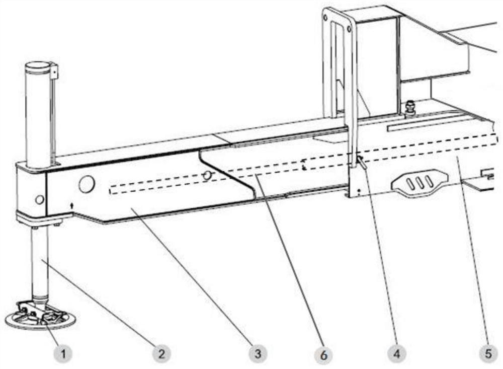
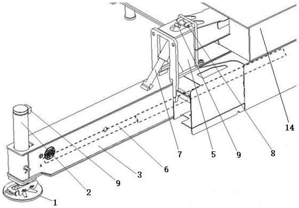
[0029] The variable lap length outrigger structure proposed by the present invention mainly includes: frame 14, fixed outriggers 5, movable outriggers 3, vertical oil cylinder 2, foot plate 1, horizontal oil cylinder 6, support oil cylinder 7, pin shaft 8, hydraulic Two-way lock 9. Hydraulic oil pipe.

[0030] One end of the horizontal oil cylinder 6 is fixed on the fixed outrigger 5, and the other end is fixed on the movable outrigger 3, and the main function is to drive the movable outrigger 3 to move.

[0031] The fixed outrigger 5 is a box-shaped structure, which is formed by tailor welding of plates, and is used to connect the movable outrigger 3 and the frame 14 and is welded on the frame 14 .

[0032] The movable outrigger 3 is driven by the horizontal oil cylinder 6 to move left and right in the fixed outrigger 5 . The outer end of the movable outrigger 3 can be installed with a vertical oil cylinder 2 , and the end of the vertical oil cylinder 2 is connected to the fo...

Embodiment 2

[0037] The support cylinder 7 is replaced by a retractable steel pipe structure, and is locked by a manual latch, such as Figure 5 As shown, the telescopic steel pipe includes a rotating steel pipe 12 and a sliding steel pipe 10. One end of the rotating steel pipe 12 is hinged on the fixed outrigger or the frame through the pin II, and can rotate around the hinge point. The sliding steel pipe 10 can slide in the rotating steel pipe 12. One end of the sliding steel pipe 10 can be matched with the supporting point on the movable outrigger 3 , and the rotating steel pipe 12 and the sliding steel pipe 10 are provided with corresponding pin shaft holes. During operation, the pin shaft I passes through the pin shaft holes on the sliding steel pipe 10 and the rotating steel pipe 12 to limit the relative sliding between the steel pipes. The disadvantage of this solution is that the operation efficiency is low and the use is inconvenient.


PUM


Abstract

The invention discloses a variable-lap-joint-length supporting leg structure and a wheeled crane, the variable-lap-joint-length supporting leg structure comprises a frame, a fixed supporting leg, a movable supporting leg, a vertical oil cylinder, a supporting foot disc, a horizontal oil cylinder, a telescopic supporting piece and a pin shaft, the movable supporting leg is sleeved in the fixed supporting leg, and the fixed supporting leg is fixed on the frame; one end of the horizontal oil cylinder is fixed on the fixed supporting leg, and the other end is fixed on the movable supporting leg; the outer sides of the movable supporting legs are connected with vertical oil cylinders; the lower end parts of the vertical oil cylinders are connected with supporting foot plates; one end of the telescopic supporting piece is connected with the fixed supporting leg / the frame through a pin shaft and can freely rotate around the pin shaft, the other end of the telescopic supporting piece is a free end and is of a stress structure, and the movable supporting leg is provided with a fixing structure matched with the free end of the telescopic supporting piece. The problem that in the prior art, the strength of the lap joint cannot be enhanced by increasing the lap joint length is solved.

Description

technical field [0001] The invention relates to a variable lap length outrigger structure and a wheeled crane, belonging to the technical field of construction machinery. Background technique [0002] As the main equipment in the lifting industry, wheeled cranes are widely used in modern construction. In order to improve the lifting capacity and stability of wheeled cranes, wheeled cranes are mostly equipped with outrigger structures. Among many outrigger structures, the H-type outrigger is the most widely used. The H-type outrigger is usually composed of 4 movable outriggers, and each movable outrigger is controlled by a separate horizontal oil cylinder to extend and retract its length. [0003] Typical wheeled cranes hoist load-bearing elements such as figure 1 As shown, it mainly includes: frame, fixed outrigger 5, movable outrigger 3, vertical oil cylinder 2, and foot plate 1. Inside the movable outrigger 3, there is a horizontal oil cylinder 6 that drives the movable o...

Claims


Application Information

Patent Timeline
Patent Type & Authority Applications(China)
IPC IPC(8): B66C23/78B66C23/80
CPCB66C23/78B66C23/80
Inventor 马云超赵建国张加丽李宝桐程伟曹希存刘建利
Owner XUZHOU HEAVY MASCH CO LTD
Why Eureka
Try Eureka