Continuous truss hydraulic bolt lifting system
A lifting system, continuous technology, applied in the field of lifting systems, can solve the problems of high cost, unadjustable lifting speed, difficult manufacturing, etc., to meet application requirements, improve reliability, and expand the scope of application.
- Summary
- Abstract
- Description
- Claims
- Application Information
AI Technical Summary
Problems solved by technology
Method used
Image

Examples
Example Embodiment
[0056] Example 1:
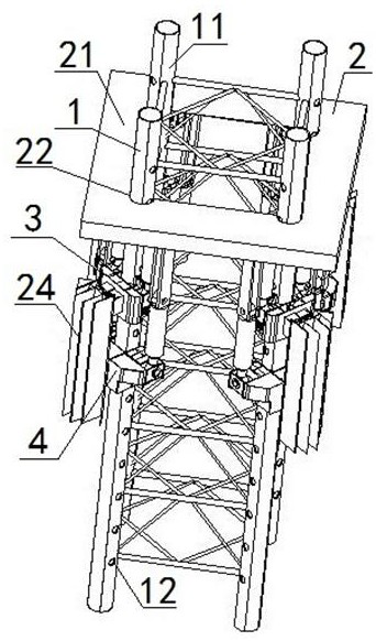
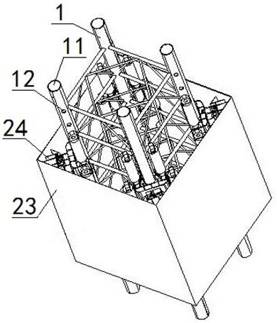
[0057]The lifting system includes: truss pile legs 1, pile fixing frames 2, four upper yoke mechanisms 3, four lower yoke mechanisms 4 and bolt assemblies 5; the truss pile legs 1 are sleeved with a pile fixing frame 2, so The middle part of the pile fixing frame 2 is provided with an opening which is matched with the truss leg 1. The truss leg 1 includes four chord tubes 11 parallel to each other, and the two sides of the chord tube 11 are evenly distributed from top to bottom. There are a plurality of pin holes 12, and the pin holes 12 are arranged in the horizontal direction. An upper yoke mechanism 3 and a lower yoke mechanism 4 are sequentially sleeved on the chord 11 from top to bottom. The bottom is fixedly connected with the cylinder seat of the upper lifting oil cylinder 31 arranged on the top of the upper yoke mechanism 3, and the bottom of the pile fixing frame 2 is fixedly connected with the cylinder seat of the lower lifting oil cylinder 41 arr...
Example Embodiment
[0063] Example 2:
[0064] Example 2 is basically the same as Example 1, except that:
[0065] The latch assembly 5 also includes two elastic centering devices 57 , the elastic centering devices 57 include a spring bracket 571 , a spring 572 , a spring guide block 573 and a nylon plate 574 , and the two elastic centering devices 57 are fixed by the spring bracket 571 . On the end face of the bolt seat 51 near the bolt cylinder 53, two elastic centering devices 57 are respectively arranged on both sides of the bolt bracket 52, one end of the spring 572 is fixedly connected with the spring bracket 571, and the other end of the spring 572 is connected by a spring The guide block 573 is fixedly connected with the contact end of the guide rod 55 . The plug assembly 5 further includes an oil injection pipe 58 , and the oil injection pipe 58 is fixedly arranged on the side of the plug 54 near the plug cylinder 53 .
Example Embodiment
[0066] Example 3:
[0067] Example 3 is basically the same as Example 2, except that:
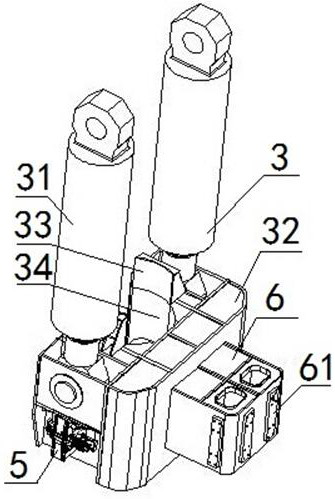
[0068] The upper yoke mechanism 3 and the lower yoke mechanism 4 are also fixedly provided with an anti-rotation mechanism 6. The anti-rotation mechanism 6 is a block structure, and the anti-rotation mechanism 6 is arranged near the limit plate 24. Two wear-resistant plates 61 are fixedly arranged on the end surface near the limit plate 24 , and one wear-resistant plate 61 is fixedly arranged on the end surfaces on both sides of the anti-rotation mechanism 6 . The limit plate 24 is matched.
PUM
 Abstract
Description
Claims
Application Information
 - R&D Engineer
- R&D Manager
- IP Professional
- Industry Leading Data Capabilities
- Powerful AI technology
- Patent DNA Extraction
Browse by: Latest US Patents, China's latest patents, Technical Efficacy Thesaurus, Application Domain, Technology Topic.
© 2024 PatSnap. All rights reserved.Legal|Privacy policy|Modern Slavery Act Transparency Statement|Sitemap