Tension control device for continuous winding of yarn

A tension control and yarn technology, applied in the field of yarn, can solve the problems of poor yarn tension adjustment effect and inability to accurately adjust the tension, and achieve the effects of improving accuracy, avoiding knots and uniform tension

Active Publication Date: 2022-07-01
常州同维佳业新材料科技有限公司
View PDF20 Cites 2 Cited by
  • Summary
  • Abstract
  • Description
  • Claims
  • Application Information

AI Technical Summary

Problems solved by technology

[0004] The purpose of the present invention is to provide a tension control device for continuous yarn winding, so as to solve the problem that the traditional tension control device for continuous yarn winding proposed in the above background technology has poor adjustment effect on yarn tension and cannot accurately adjust the tension. Regulatory issues

Method used


Image

  • Tension control device for continuous winding of yarn
  • Tension control device for continuous winding of yarn
  • Tension control device for continuous winding of yarn

Examples


Embodiment 1

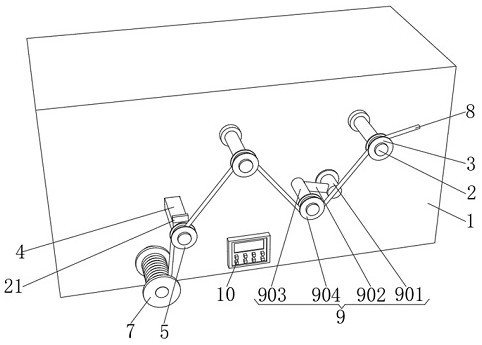
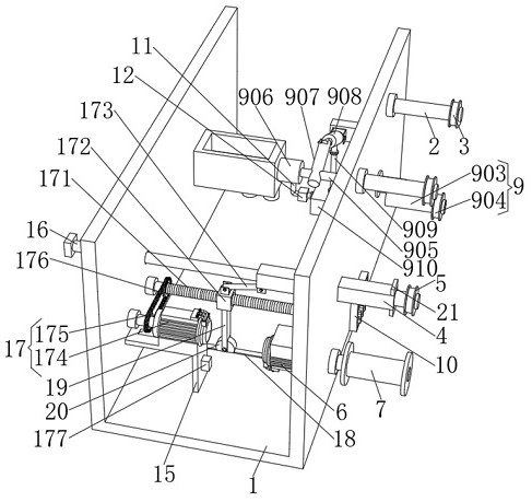
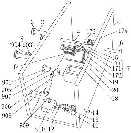
[0027] see Figure 1-6 , the present invention provides a technical solution: a tension control device for continuous yarn winding, comprising an installation frame 1, and two sets of fixed rods 2 are installed on the top of the front of the installation frame 1 to rotate along the left-right direction, and the fixed rods 2 are fixed on the A fixed guide wheel 3 is connected, a fixed rod 4 is inserted on the left side of the bottom of the front of the installation frame 1, and the fixed rod 4 is located on the left side of the fixed rod 2, and the front of the fixed rod 4 is fixedly connected with the adjustment wheel 5 through the cable rod. The frame 1 is provided with a reciprocating mechanism 17 that is used in conjunction with the adjusting wheel 5. The design of the reciprocating mechanism 17 uses the second motor 174 to provide a driving source, which can push the adjusting wheel 5 to reciprocate according to the line distance required by the product, so that the yarn T...

Embodiment 2

[0029] see Figure 1-6, the present invention provides a technical solution: a tension control device for continuous yarn winding, comprising an installation frame 1, and two sets of fixed rods 2 are installed on the top of the front of the installation frame 1 to rotate along the left-right direction, and the fixed rods 2 are fixed on the A fixed guide wheel 3 is connected, a fixed rod 4 is inserted on the left side of the bottom of the front of the installation frame 1, and the fixed rod 4 is located on the left side of the fixed rod 2. The fixed rod 4 has a square structure, which can prevent the fixed rod 4 from rotating when moving. The front of the fixing rod 4 is fixedly connected with the adjusting wheel 5 through the cable rod, and the fronts of the top and bottom of the fixing rod 4 are fixedly connected with baffles 21, which can limit the front of the fixing rod 4 and prevent the fixing rod 4 from entering the installation completely. Frame 1, it is easy to make th...


PUM


Abstract

The invention relates to the technical field of yarns, and discloses a tension control device for continuous winding of yarns, which comprises a mounting frame, two groups of fixed rods are rotatably mounted at the top of the front surface of the mounting frame in the left-right direction, fixed guide wheels are fixedly connected to the fixed rods, and fixed rods are inserted in the left side of the bottom of the front surface of the mounting frame and located on the left sides of the fixed rods; the front face of the fixing rod is fixedly connected with an adjusting wheel through a yarn arranging rod, a reciprocating mechanism used in cooperation with the adjusting wheel is arranged in the mounting frame, the left side of the back face of an inner cavity of the mounting frame is fixedly connected with a first motor through a support, and the output end of the first motor penetrates through the mounting frame and is fixedly connected with a yarn coil pipe. According to the yarn winding device, by means of the auxiliary mechanism and the controller, the movement speed of the first motor can be controlled according to different tension of the yarn, so that it can be guaranteed that the tension of the yarn is uniform, and then it can be guaranteed that the yarn is continuously wound.

Description

technical field [0001] The invention relates to the technical field of yarn, in particular to a tension control device for continuous yarn winding. Background technique [0002] Yarn is a kind of textile, which is processed into products of a certain fineness with various textile fibers. It is used for weaving, rope making, thread making, knitting and embroidery, etc. It is divided into short fiber yarn, continuous filament, etc. When the thread is processed, the yarn needs to be wound. When winding, the tension control device needs to be used to adjust the tension of the yarn, so as to ensure that the yarn can be wound normally. [0003] However, the traditional tension control device for continuous yarn winding has poor adjustment effect on the yarn tension and cannot precisely adjust the tension, resulting in the yarn being too slack or too tight during the winding process, which makes it easy to wind the yarn. Knots and breaks, for this purpose, a tension control device...

Claims


Application Information

Patent Timeline
Patent Type & Authority Applications(China)
IPC IPC(8): B65H59/38B65H54/547B65H54/44B65H54/70B65H54/30
CPCB65H59/385B65H54/547B65H54/44B65H54/70B65H54/30B65H2701/31
Inventor 陈志伟陈菁钟大彭周荷萍
Owner 常州同维佳业新材料科技有限公司
Why Eureka
Try Eureka