
Cycloidal pin gear speed reducer and assembling method thereof

A cycloidal pinwheel deceleration and assembly method technology, which is applied in the direction of assembly machines, mechanical equipment, transmission parts, etc., can solve the problems of improving repair quality, long working hours of assembly technology, disadvantages, etc., to achieve improved work efficiency, convenient assembly and Fast, quality-assured results

Pending Publication Date: 2022-07-01
CHONGQING IRON & STEEL CO LTD
View PDF0 Cites 0 Cited by
  • Summary
  • Abstract
  • Description
  • Claims
  • Application Information

AI Technical Summary

Problems solved by technology

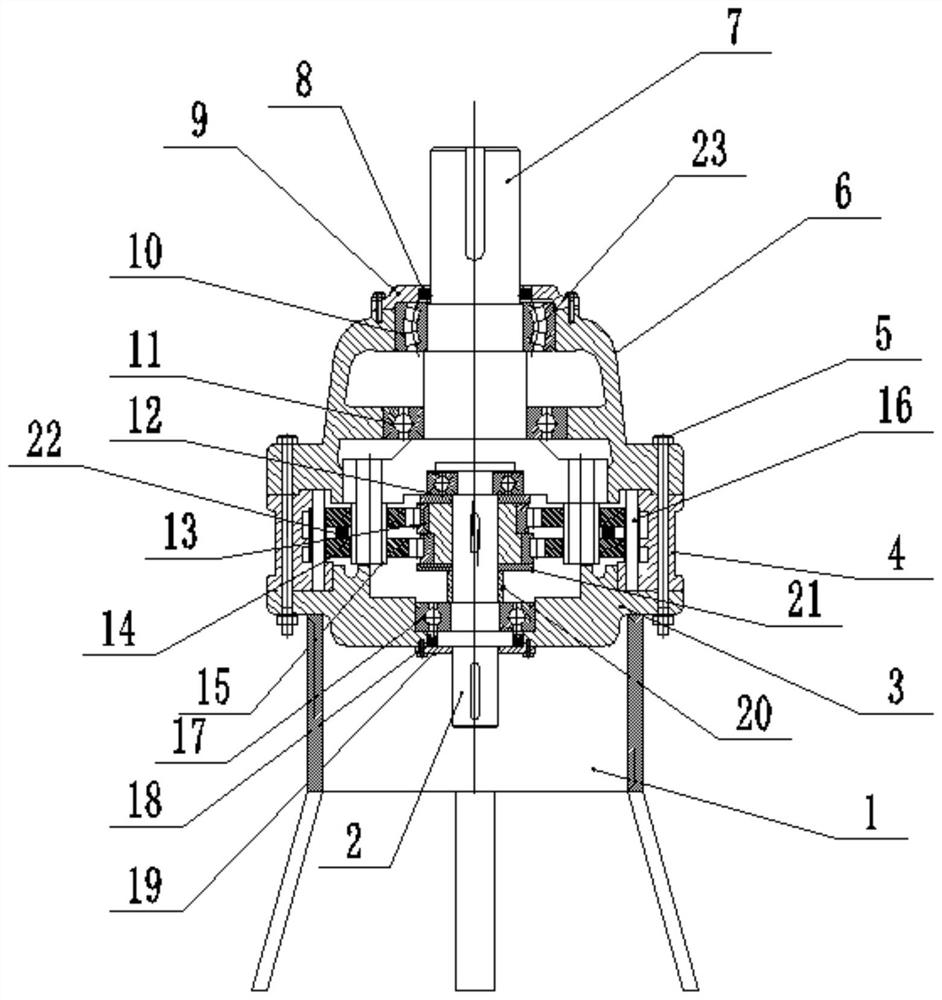
[0003] In view of this, the purpose of the present invention is to provide a cycloidal pinwheel reducer and its assembly method, which completely changes the existing assembly method and repair process, and solves the technical problems that the existing assembly technology has a long working time and is not conducive to improving the repair quality.

Method used


Image

  • Cycloidal pin gear speed reducer and assembling method thereof
  • Cycloidal pin gear speed reducer and assembling method thereof

Examples


Embodiment Construction

[0032] The embodiments of the present invention are described below through specific specific examples, and those skilled in the art can easily understand other advantages and effects of the present invention from the contents disclosed in this specification. The present invention can also be implemented or applied through other different specific embodiments, and various details in this specification can also be modified or changed based on different viewpoints and applications without departing from the spirit of the present invention. It should be noted that the drawings provided in the following embodiments are only used to illustrate the basic idea of ​​the present invention in a schematic manner, and the following embodiments and features in the embodiments can be combined with each other without conflict.

[0033] Among them, the accompanying drawings are only used for exemplary description, and represent only schematic diagrams, not physical drawings, and should not be ...


PUM


Abstract

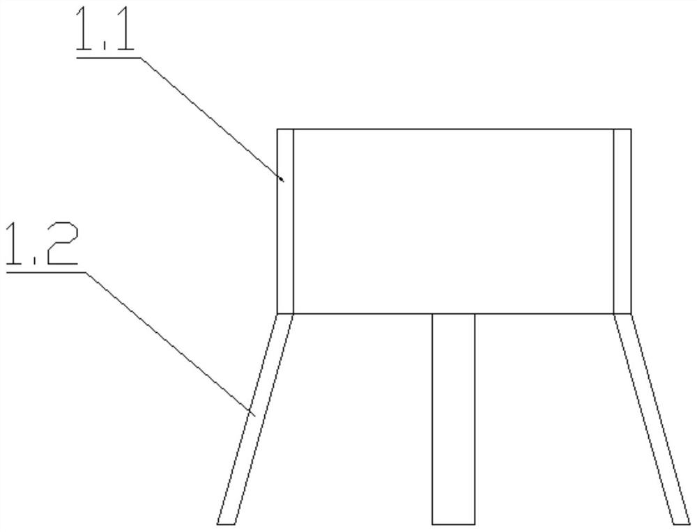
The invention relates to a cycloidal pin gear speed reducer and an assembling method thereof, and belongs to the field of speed reducer installation. The method comprises the steps that S1, a tool auxiliary device is arranged; s2, mounting an input shaft assembly; s3, the input end box body is inversely arranged on the tool auxiliary device; s4, the input shaft assembly is installed on the input end box body; s5, the middle section box body is installed on the input end box body; a sleeve; s6, mounting an output shaft assembly; s7, the output shaft assembly is installed on the swing piece of the middle section box body, and the output shaft assembly is connected with the input shaft assembly; s8, the output shaft assembly is sleeved with the output end box body; and S9, an output shaft sealing ring and an input shaft sealing ring are installed on the input shaft and the output shaft and sealed through an input end sealing end cover and an output end sealing end cover, and the output end box body, the middle section box body and the input end box body are connected and fixed through connecting bolts. The technical problems that an existing assembling technology is long in working time and not beneficial to improvement of repairing quality are solved.

Description

technical field [0001] The invention belongs to the field of reducer installation, in particular to a cycloidal pinwheel reducer and an assembling method thereof. Background technique [0002] The assembly of the cycloidal pinwheel reducer is now to assemble the interrupted eccentric sleeve assembly after the high-speed shaft assembly and the output shaft assembly are assembled separately; finally, the three sections are combined into a whole. And the bearing at the rear end of the input shaft needs to be assembled into the hole of the output shaft assembly at the same time, so that the synchronous operation cannot see the internal situation with the naked eye, and the hand cannot perceive the internal contact situation, which will have a certain impact on the effect after assembly, and it may even be assembled. If it is not in place, it is necessary to perform multiple rework operations, which wastes a certain amount of work time, which is not conducive to improving the qua...

Claims


Application Information

Patent Timeline
IPC IPC(8): F16H57/023F16H57/02F16H57/021F16H57/029B23P21/00
CPCF16H57/023F16H57/02F16H57/021F16H57/029B23P21/00F16H2057/02021
Inventor 黎长友文向东包妍琳马宁辉张力文刘朝军李欣雨傅玉娇付先艳皮春兰
Owner CHONGQING IRON & STEEL CO LTD
Learn More