Supercharge Your Innovation With Domain-Expert AI Agents!

Voltage control method

A voltage control method and voltage value technology, applied to electrical components, output power conversion devices, etc., to achieve the effects of improving instantaneous response speed, improving ripple, and reducing instantaneous variation

Pending Publication Date: 2022-07-01
致茂电子(苏州)有限公司
View PDF0 Cites 0 Cited by
  • Summary
  • Abstract
  • Description
  • Claims
  • Application Information

AI Technical Summary

Problems solved by technology

[0004] The technical problem to be solved in this application is to provide a voltage control method, which can dynamically adjust the gain value to improve the ripple problem during low voltage output, and can also improve the instantaneous response speed when pulling heavy loads

Method used


Image

  • Voltage control method
  • Voltage control method
  • Voltage control method

Examples


Embodiment Construction

[0017] The positional relationships described in the following embodiments, including: up, down, left and right, are based on the directions shown by the components in the drawings unless otherwise specified.

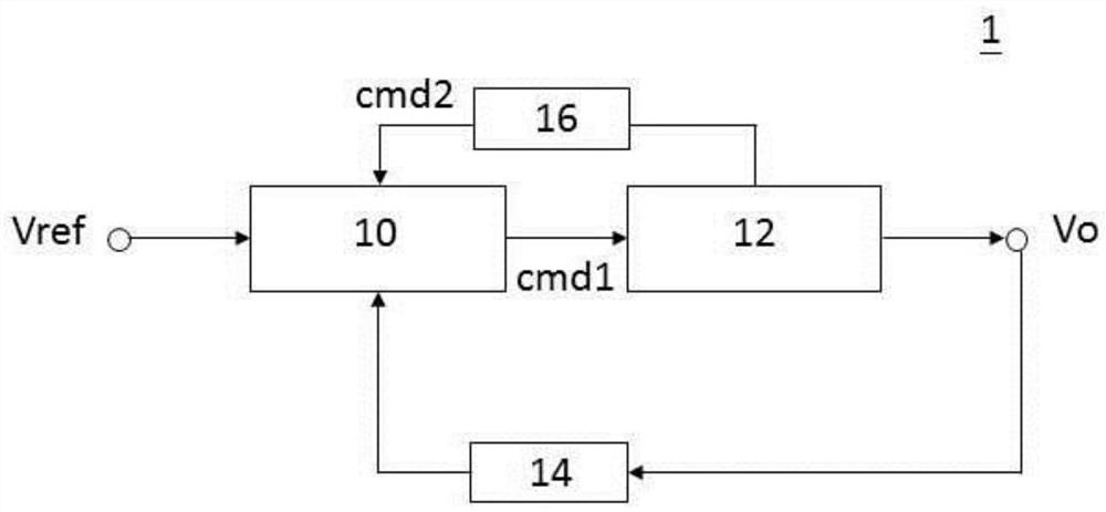
[0018] Please refer to figure 1 , figure 1 It is a functional block diagram of a power supply applying a voltage control method according to an embodiment of the present application. like figure 1 As shown, the voltage control method of the present application can be applied to a power supply system, such as the power supply 1 . The power supply 1 may include a control unit 10 , a voltage output unit 12 , a voltage measurement unit 14 and an inductor current measurement unit 16 . Here, the control unit 10 may be electrically connected to the voltage output unit 12 , the voltage measurement unit 14 and the inductor current measurement unit 16 , respectively. In one example, the voltage output unit 12 may be a buck converter or other PWM voltage converter. The output...


PUM


Abstract

The invention provides a voltage control method, which is used for controlling a power supply and comprises the following steps. Obtaining a current output voltage value, wherein the current output voltage value is associated with the current gain value; a predetermined output voltage value is obtained, wherein the predetermined output voltage value is associated with a predetermined duty cycle. Thirdly, calculating a target gain value corresponding to the preset duty ratio according to a gain value corresponding formula; and performing weight calculation on the current gain value and the target gain value to generate a buffer gain value. And finally, setting an output voltage command according to the buffer gain value. Wherein the buffer gain value is between the current gain value and the target gain value.

Description

technical field [0001] The present application relates to a voltage control method, in particular to a voltage control method that can dynamically adjust the gain value. Background technique [0002] In order to provide a stable output voltage to the load, the traditional power system usually uses a feedback mechanism to monitor the output voltage. For example, it is common practice to make the output voltage track a reference voltage so that the output voltage can be more controllable. In general, in order to maintain the output voltage efficiency under heavy loading, traditional power systems choose to use larger gain values. However, in some usage scenarios, such as light loading or floating, using a larger gain value will result in more obvious ripples at low output voltages, and the ripples Waves have the potential to cause the power system to not meet customer specifications. On the contrary, if you choose to use a smaller gain value to solve the problem of ripple, ...

Claims


Application Information

Patent Timeline
Patent Type & Authority Applications(China)
IPC IPC(8): H02M1/00H02M1/32
CPCH02M1/00H02M1/32
Inventor 林胜雄蔡欣洋罗文期
Owner 致茂电子(苏州)有限公司
Features
  • R&D
  • Intellectual Property
  • Life Sciences
  • Materials
  • Tech Scout
  • Unparalleled Data Quality
  • Higher Quality Content
  • 60% Fewer Hallucinations
Learn More