
Lock clamp extractor

A technology of extractor and locking clip, which is applied in the direction of joint implants and joint implants, and can solve the problems of difficult removal of locking devices

Active Publication Date: 2022-07-08
BEIJING AKEC MEDICAL
View PDF12 Cites 0 Cited by
  • Summary
  • Abstract
  • Description
  • Claims
  • Application Information

AI Technical Summary

Problems solved by technology

[0006] The main purpose of the present invention is to provide a lock clip remover to solve the problem of difficulty in taking out the locking device from the fixing groove in the related art

Method used


Image

  • Lock clamp extractor
  • Lock clamp extractor
  • Lock clamp extractor

Examples


Embodiment Construction

[0035] The technical solutions in the embodiments of the present invention will be clearly and completely described below with reference to the accompanying drawings in the embodiments of the present invention. Obviously, the described embodiments are only a part of the embodiments of the present invention, but not all of the embodiments. The following description of at least one exemplary embodiment is merely illustrative in nature and is in no way intended to limit the invention, its application, or uses. Based on the embodiments of the present invention, all other embodiments obtained by those of ordinary skill in the art without creative efforts shall fall within the protection scope of the present invention.

[0036] It should be noted that the terminology used herein is for the purpose of describing specific embodiments only, and is not intended to limit the exemplary embodiments according to the present application. As used herein, unless the context clearly dictates ot...


PUM


Abstract

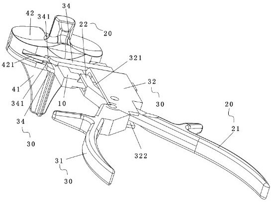
The invention provides a lock clamp extractor, which comprises a base body, which comprises an insertion part and a connection part forming an angle with the insertion part, and the insertion part can be inserted and fixed in a fixing groove for placing a lock clamp; the first operating handle comprises a first handle body and a force application straight section connected with the end of the first handle body, and the force application straight section abuts against the connecting part; the second operating handle comprises a second handle body hinged to the first handle body through a hinged shaft, a guide section connected with the end of the second handle body and a horizontal force application section connected with the guide section, the horizontal force application section can apply thrust to the end of the lock clamp, and the guide section is in horizontal guide fit with the connecting part; the horizontal force application section protrudes out of the insertion part in the insertion direction of the insertion part. According to the technical scheme, the problem that in the prior art, it is difficult to take out the locking device from the fixing groove is effectively solved.

Description

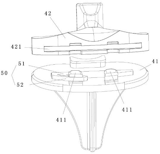
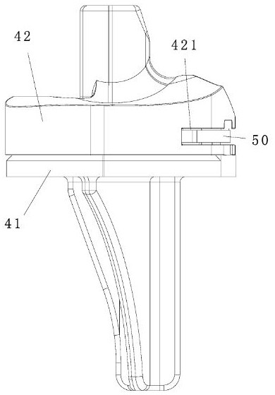
technical field [0001] The invention relates to the field of medical instruments, in particular to a lock clip extractor. Background technique [0002] Artificial joint replacement is suitable for patients with severe joint pain, instability, deformity, severe limitation of daily life and activities, and ineffective or ineffective after conservative treatment. like figure 1 and figure 2 As shown, the artificial knee joint generally consists of a tibial plateau 41, a tibial spacer 42 and a femoral condyle. [0003] The problem that the tibial plateau 41 and the tibial spacer 42 of the artificial knee joint in the prior art are locked together is a difficult point. The industry uses various means to lock the tibial plateau 41 and the tibial spacer 42. Among them, the related art A locking device 50 is provided for enabling the tibial plateau 41 and the tibial spacer 42 to be locked together. [0004] The above-mentioned anti-detachment structure between the first side por...

Claims


Application Information

Patent Timeline
IPC IPC(8): A61F2/46
CPCA61F2/461A61F2/4637A61F2002/4615A61F2002/4619A61F2002/4622A61F2002/4641
Inventor 王彩梅胡瑞峥全昌贵
Owner BEIJING AKEC MEDICAL
Learn More