Computer memory bank cleaning device

A technology for cleaning devices and memory sticks, which can be applied to cleaning methods and utensils, cleaning methods using tools, chemical instruments and methods, etc., and can solve the problems of low cleaning efficiency, increased labor intensity of users, and inability to collect debris.

Active Publication Date: 2022-07-08
SHANDONG VOCATIONAL COLLEGE OF SCI & TECH
View PDF22 Cites 0 Cited by
  • Summary
  • Abstract
  • Description
  • Claims
  • Application Information

AI Technical Summary

Problems solved by technology

[0002] The memory stick is an essential part of the computer. Any kind of input (from external storage, keyboard, mouse, microphone, scanner, etc.) All of them can only be done through the memory, and when the memory stick inserted into the computer is used for a long time, the golden fingers in the memory stick will be dirty due to the accumulation of dust in the air, which may lead to dust generated by the memory stick. Static electricity breaks down the computer
[0003] Most of the existing memory sticks are manually cleaned, but limited by the strength of the operator, it may cause incomplete cleaning due to too little force or damage to the memory stick due to excessive force. On the other hand, simple Using an eraser to clean the memory sticks cannot effectively collect the cleaned debris. When a large number of memory sticks need to be cleaned, it will not only lead to low cleaning efficiency, but also increase the labor intensity of the user.
[0004] In summary, there are obviously inconveniences and defects in the actual use of the existing technology, so it is necessary to improve

Method used


Image

  • Computer memory bank cleaning device
  • Computer memory bank cleaning device
  • Computer memory bank cleaning device

Examples


Embodiment Construction

[0018] In order to make the objectives, technical solutions and advantages of the present invention clearer, the present invention will be further described in detail below with reference to the accompanying drawings. It should be understood that the specific embodiments described herein are only used to explain the present invention, but not to limit the present invention.

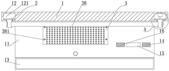
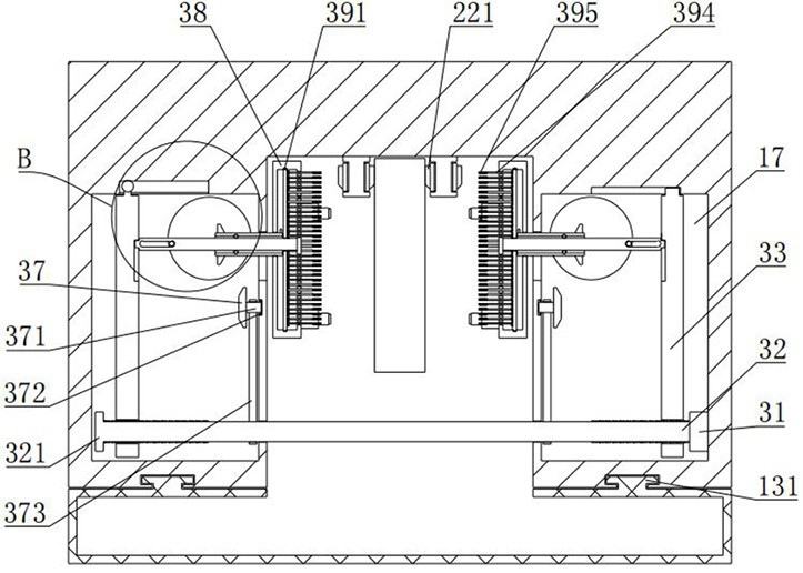
[0019] see Figure 1~Figure 7 , the present invention provides a computer memory stick cleaning device, including a box body 1, a moving component 2 and a cleaning component 3, the bottom of the box body 1 is provided with a receiving groove 11 that runs through the box body 1 in the horizontal direction, and the memory stick is in the receiving groove 11. cleaning inside.

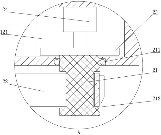
[0020] see Figure 1~Figure 3 , the moving assembly 2 includes a connecting shaft 21 , a first bearing 211 , a limiting groove 212 , a conveyor belt 22 , a gear 23 and a first driving member 24 . Two mounting seats 12 are fixedly c...


PUM


Abstract

The invention is suitable for the technical field of memory bank cleaning, and provides a computer memory bank cleaning device, which comprises a box body, a storage box, a storage box and a storage box, the moving assembly comprises mounting bases, the mounting bases are arranged at the two ends of the box body, each mounting base is rotationally connected with two connecting shafts, and a conveying belt is arranged between the corresponding connecting shafts; the cleaning assembly comprises a moving plate, the moving plate is arranged in the box body, a connecting rod is arranged on the moving plate in a sliding mode, the connecting rod is connected with a cleaning seat, a jacking column is arranged on the cleaning seat, a rotating wheel is arranged in the box body, a shifting rod is arranged on the rotating wheel, a connecting plate is arranged in the cleaning seat, the connecting plate is connected with a brush rod, a third brush is arranged on the brush rod, and a sleeve is rotationally arranged on the connecting rod in a sleeving mode; a push rod is arranged on the sleeve, a plurality of push columns are arranged on the connecting plate, a second bevel gear is arranged in the box body, and a first bevel gear is arranged on the sleeve. Therefore, the memory bank can be automatically, comprehensively and effectively cleaned, the memory bank can be prevented from being damaged in the cleaning process, the manufacturing cost is low, and the practicability is high.

Description

technical field [0001] The invention relates to the technical field of memory stick cleaning, in particular to a computer memory stick cleaning device. Background technique [0002] Memory stick is an essential part of the computer, any kind of input (from external memory, keyboard, mouse, microphone, scanner, etc.) and any kind of output (display, printing, audio-visual, writing to external memory, etc.) All can be done through the memory, and when the memory stick inserted into the computer is used for a long time, the gold fingers in the memory stick will become dirty due to the accumulation of dust in the air, which may lead to damage caused by dust. A situation where electrostatic breakdown occurs in the computer. [0003] Most of the existing memory sticks are cleaned manually, but limited by the operator's strength, it may cause incomplete cleaning due to too little force or damage to the memory stick due to too much force. Cleaning the memory sticks with an eraser ...

Claims


Application Information

Patent Timeline
IPC IPC(8): B08B1/00B08B1/02
CPCB08B1/143B08B1/30B08B1/20B08B1/12
Inventor 李美芹姚勋勋
Owner SHANDONG VOCATIONAL COLLEGE OF SCI & TECH
Why Eureka
Try Eureka