Eureka AIR delivers breakthrough ideas for toughest innovation challenges, trusted by R&D personnel around the world.

Strip rolling mill comprehensive fault simulation test bench considering multidirectional loading working condition

A technology for simulating test benches and comprehensive faults. It is used in mechanical bearing testing, mechanical component testing, and machine/structural component testing. It can solve problems such as difficulty in data collection, inaccuracy, and inability to simulate test data, and achieve accurate loads. Size, control load size, cleverly conceived effects

Pending Publication Date: 2022-07-08
YANSHAN UNIV
View PDF9 Cites 0 Cited by
  • Summary
  • Abstract
  • Description
  • Claims
  • Application Information

AI Technical Summary

Problems solved by technology

However, the fault monitoring and diagnosis of rolling mill multi-row rolling bearings and gearbox gears under real rolling conditions have not been demonstrated on the production site or in the laboratory, mainly because the on-site rolling environment is harsh, the types of faults are complex, and the data collection is very difficult. Difficult, the test accuracy cannot be guaranteed, and secondly, if it is in the laboratory, the actual rolling conditions cannot be simulated and the test data is inaccurate and other problems

Method used


Image

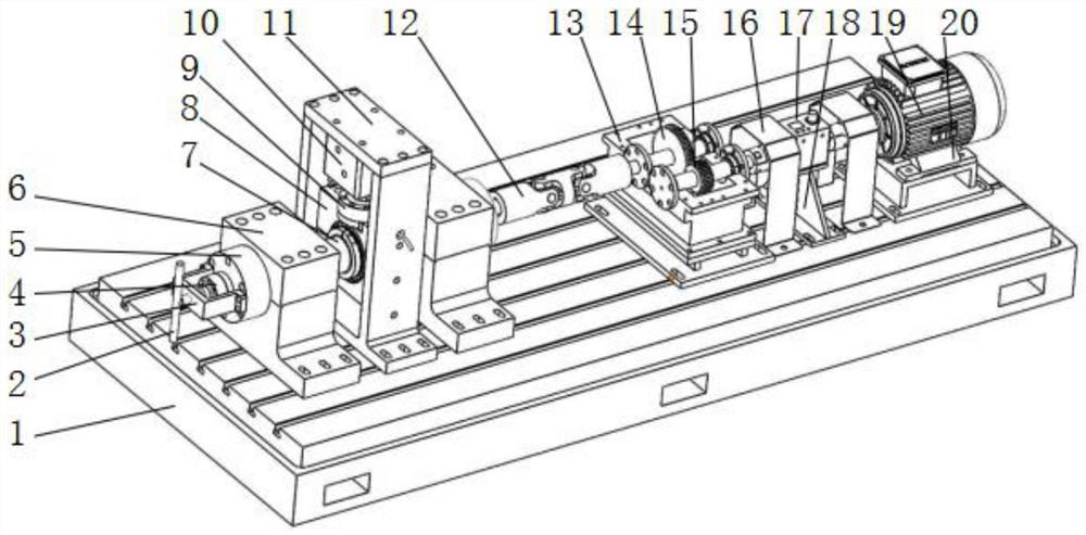
  • Strip rolling mill comprehensive fault simulation test bench considering multidirectional loading working condition
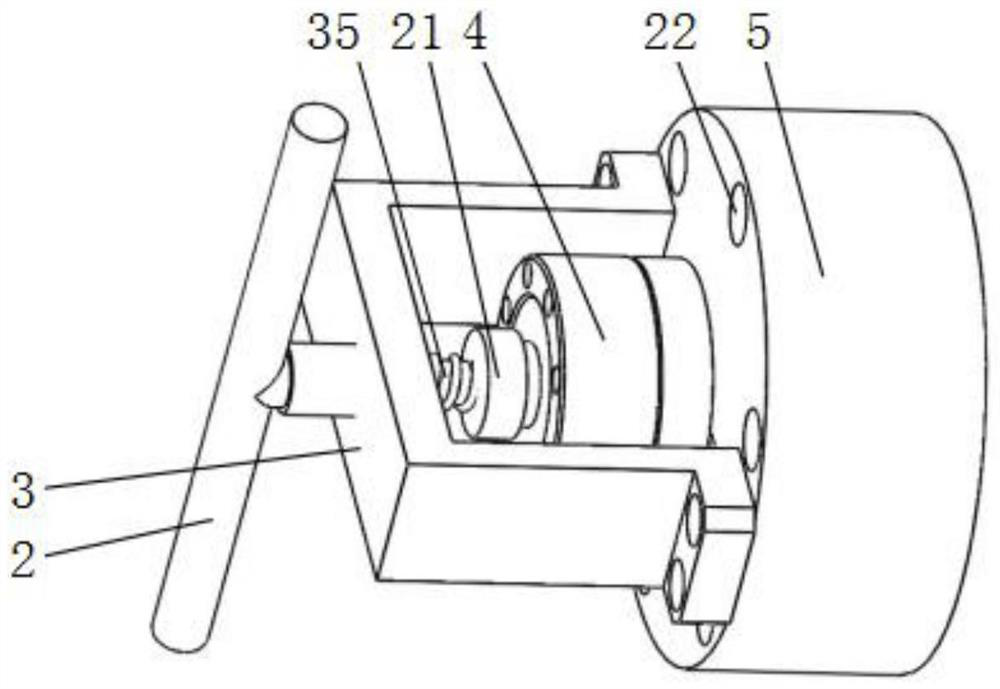
  • Strip rolling mill comprehensive fault simulation test bench considering multidirectional loading working condition
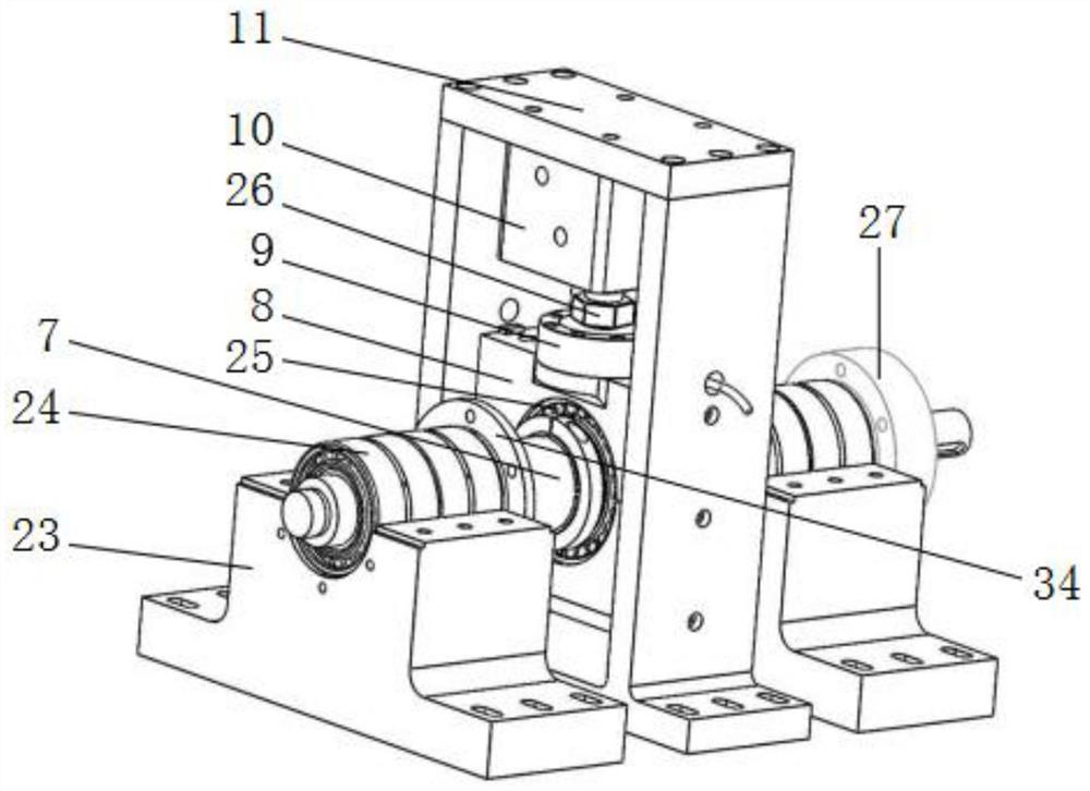
  • Strip rolling mill comprehensive fault simulation test bench considering multidirectional loading working condition

Examples


Embodiment Construction

[0024] In order to illustrate the embodiments of the present invention or the technical solutions in the prior art more clearly, the following briefly introduces the accompanying drawings that need to be used in the description of the embodiments or the prior art. Obviously, the accompanying drawings in the following description These are some embodiments of the present invention. For those of ordinary skill in the art, other drawings can also be obtained according to these drawings without creative efforts.

[0025] It should be noted that in the description of the present invention, the terms "upper", "lower", "top", "bottom", "one side", "the other side", "left", "right", etc. The orientation or positional relationship is based on the orientation or positional relationship shown in the drawings, and is only for the convenience of describing the present invention and simplifying the description, and does not mean that a device or element must have a specific orientation, be c...


PUM


Abstract

The invention relates to a plate and strip rolling mill comprehensive fault simulation test bench considering a multi-directional loading working condition. The test bench comprises a base, an axial loading assembly, a movable radial hydraulic loading assembly, a speed change gear box assembly, a rotating speed and torque control assembly and rollers. The axial loading assembly, the movable radial hydraulic loading assembly, the speed change gear box assembly and the rotating speed and torque control assembly are sequentially arranged on the upper end face of the base. The roller is axially arranged in the middle of the movable radial hydraulic loading assembly; the axial loading assembly is fixedly connected with one end of the movable radial hydraulic loading assembly, and one end of the roller is located in the axial loading assembly. The other end of the roller is connected with one end of the speed change gear box assembly; the other end of the speed change gear box assembly is connected with the rotating speed and torque control assembly. According to the invention, comprehensive faults of multiple rows of rolling bearings and gears under a multidirectional loading working condition can be simulated, and a rolling force unbalance loading effect, a roller system crossing phenomenon and variable working condition rolling can also be simulated.

Description

technical field [0001] The invention relates to the technical field of fault monitoring and diagnosis of rotating machinery, in particular to a comprehensive fault simulation test bench for a strip rolling mill considering multi-directional loading conditions. Background technique [0002] With the development of high-strength, thin-strip steel strip products such as automobile sheets, home appliance sheets, and aviation sheets, the workload of rolling equipment is bound to increase. High-load, high-speed production processes and harsh production environments inevitably induce various rolling mill failures. Among them, the multi-row rolling bearing of the roller series, the gear box bearing and the gear are the key components to bear and transmit the rolling force and torque. They are subjected to various superimposed loads and variable working conditions, resulting in frequent failures, including pitting, Single faults such as wear, indentation and tooth surface gluing, as...

Claims


Application Information

Patent Timeline
IPC IPC(8): G01M13/021G01M13/04G01M13/027G01M13/028G01M13/045
CPCG01M13/021G01M13/04G01M13/027G01M13/028G01M13/045
Inventor 孙建亮吝水林马超郭鑫赵琛曾骄
Owner YANSHAN UNIV
Why Eureka
Eureka Blog
Learn More