Outdoor power distribution cabinet with dust removal mechanism

A power distribution cabinet and outdoor technology, which is applied in the field of outdoor power distribution cabinets with a dust removal mechanism, can solve the problems that the heat dissipation network is difficult to remove dust, and the heat dissipation network is blocked by the normal heat dissipation of the power distribution cabinet, so as to prevent electrical components from being damaged due to short circuit, Reasonable structure, the effect of improving sealing performance

Pending Publication Date: 2022-07-08
安徽蓝润正华电子有限公司
View PDF0 Cites 0 Cited by
  • Summary
  • Abstract
  • Description
  • Claims
  • Application Information

AI Technical Summary

Problems solved by technology

[0004] The purpose of the present invention is to solve the problem that the hard-to-remove dust adheres to the heat dissipation net of the power distribution cabinet in the prior art, which causes the blockage of the heat dissipation net and affects the normal heat dissipation of the power distribution cabinet, and proposes an outdoor dust removal mechanism. Distribution Cabinet

Method used


Image

  • Outdoor power distribution cabinet with dust removal mechanism
  • Outdoor power distribution cabinet with dust removal mechanism
  • Outdoor power distribution cabinet with dust removal mechanism

Examples


Embodiment 1

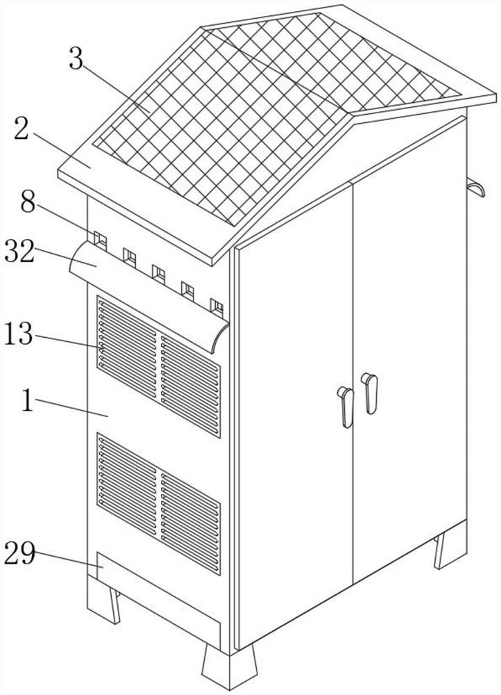
[0031] refer to Figure 1-6 , an outdoor power distribution cabinet with a dust removal mechanism, comprising a cabinet body 1, a rain shield 2 is fixedly installed on the top of the cabinet body 1, a separation net 3 is fixedly embedded on the top surface of the rain shield 2, and the separation net 3 is conducive to blocking The sundries such as leaves, sand and gravel from the outside fall into the water storage tank 5. The bottom of the separation net 3 is provided with a splitter plate 4 fixed to the top of the inner side of the cabinet 1. The inner side of the cabinet 1 is provided with a movable dust removal mechanism, which is used for matching. The dust-proof net 12 in the electric cabinet 1 and the wet dust adhering to the heat-dissipating net 13 are scraped off;

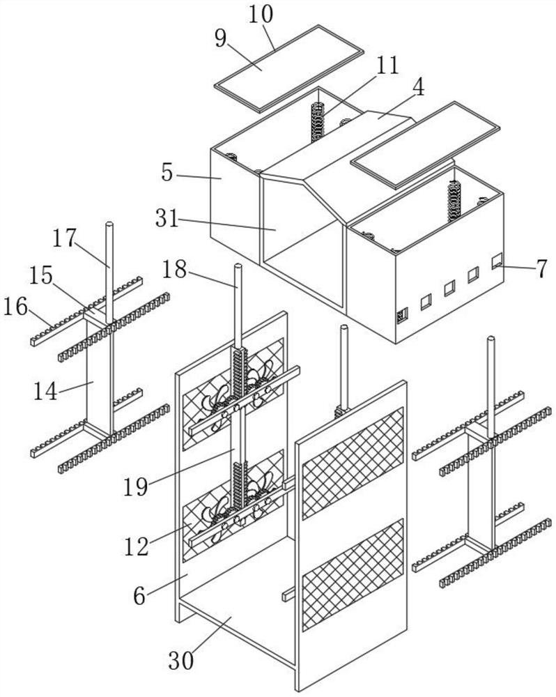
[0032] The movable dust removal mechanism includes two water storage tanks 5 and two divided vertical plates 6. The two water storage tanks 5 are respectively located at the inner ends of the top inner sid...

Embodiment 2

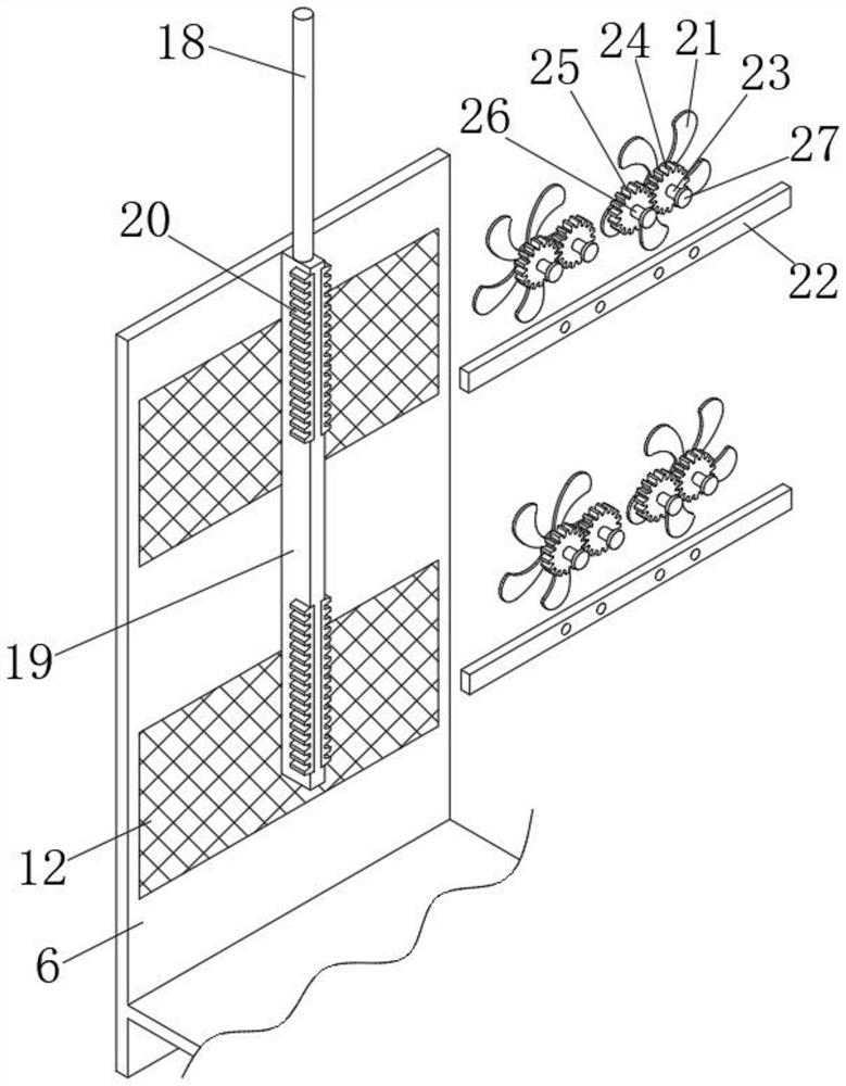
[0037] like Figure 1-5 As shown, this embodiment is basically the same as Embodiment 1. The two dust blowing assemblies both include a second push rod 18 and a movable vertical rod 19. The two second push rods 18 are located on one side of the bottom of the two water storage tanks 5 respectively. The two push rods 18 penetrate through the bottom of the water storage tank 5 and are fixedly connected to the movable plate 9. The movable vertical rod 19 is located at the bottom of the second push rod 18 and is fixedly connected to the second push rod 18. The four corners of the movable vertical rod 19 are fixedly embedded with limit teeth. Strip 20. Fan blades 21 are provided on both ends of one side of the dust-proof net 12, a fixed cross bar 22 fixed to the cabinet 1 is provided on one side of the dust-proof net 12, and a first horizontal shaft 23 is fixedly connected on one side of the fan blade 21. , the outer side of the first horizontal shaft 23 is fixedly sleeved with a fi...

Embodiment 3

[0040] like figure 2 and Figure 4 As shown, this embodiment is basically the same as Embodiment 1. A U-shaped sealing plate 31 fixed to the cabinet 1 is sealed and welded at the bottom of the manifold 4 , and the two ends of the U-shaped sealing plate 31 are sealed and welded to one end of the two water storage tanks 5 respectively.

[0041] In this embodiment, when it rains, the diverter plate 4 discharges the rainwater entering through the separation net 3 into the two water storage tanks 5 respectively. Limiting and sealing improve the sealing performance of the top of the entire power distribution cabinet, preventing rainwater from falling into the interior of the power distribution cabinet from the top of the power distribution cabinet and causing damage to electrical components due to short circuit.


PUM


Abstract

The outdoor power distribution cabinet comprises a cabinet body, a rain baffle is fixedly installed at the top of the cabinet body, a separation net is fixedly embedded in the surface of the top of the rain baffle, a splitter plate fixed to the top of the inner side of the cabinet body is arranged at the bottom of the separation net, and the movable dust removal mechanism is arranged on the inner side of the cabinet body. The movable dust removal mechanism comprises two water storage tanks and two partition vertical plates, and the two water storage tanks are located at the two ends of the inner side of the top of the cabinet body respectively and welded to the cabinet body in a sealed mode. According to the outdoor power distribution cabinet, the problems that dust adhered to a heat dissipation net in an existing outdoor power distribution cabinet is difficult to clean, so that the heat dissipation net is blocked, normal heat dissipation of the power distribution cabinet is affected, and electric appliance elements in the power distribution cabinet are damaged due to too high temperature during working are effectively solved, so that the power distribution cabinet is more convenient to clean and collect dust, and the working efficiency is improved. The sealing performance of the whole power distribution cabinet is improved, damage to electrical components due to short circuit caused by water entering the power distribution cabinet is prevented, and the service life of the power distribution cabinet is prolonged.

Description

technical field [0001] The invention relates to the technical field of power distribution cabinets, in particular to an outdoor power distribution cabinet with a dust removal mechanism. Background technique [0002] Power distribution cabinets refer to the final equipment of power distribution cabinets, lighting distribution cabinets, metering cabinets and other power distribution systems respectively. The power distribution cabinet is used in situations where the load is relatively scattered and there are few circuits; the motor control center is used in the situation where the load is concentrated and there are many circuits. At present, in areas with frequent rainfall, some power distribution cabinets need to be used outdoors. [0003] Existing outdoor power distribution cabinets are often equipped with cooling nets to dissipate heat. Due to the high humidity outdoors, the dust on the cooling nets is easily adhered to the cooling nets and is difficult to remove when enco...

Claims


Application Information

Patent Timeline
IPC IPC(8): H02B1/28H02B1/56B08B1/00B08B13/00B08B15/04
CPCH02B1/28H02B1/565B08B1/00B08B13/00B08B15/04Y02A20/108
Inventor 庄连美秦喜春
Owner 安徽蓝润正华电子有限公司
Why Eureka
Try Eureka