Drive device for vehicle

A driving device and vehicle technology, applied in transmission parts, vehicle components, electric vehicles, etc., can solve problems such as excessive load, shorten the service life of rotor shaft rotating bearings, and generate noise, and achieve the effect of reducing shaft bending stress

Pending Publication Date: 2022-07-08
AUDI AG
View PDF4 Cites 0 Cited by
  • Summary
  • Abstract
  • Description
  • Claims
  • Application Information

AI Technical Summary

Problems solved by technology

This shaft deflection can lead to excessive loading of the rotor shaft turning bearings, noise generation and reduced rotor shaft turning bearing life

Method used


Image

  • Drive device for vehicle
  • Drive device for vehicle
  • Drive device for vehicle

Examples


Embodiment Construction

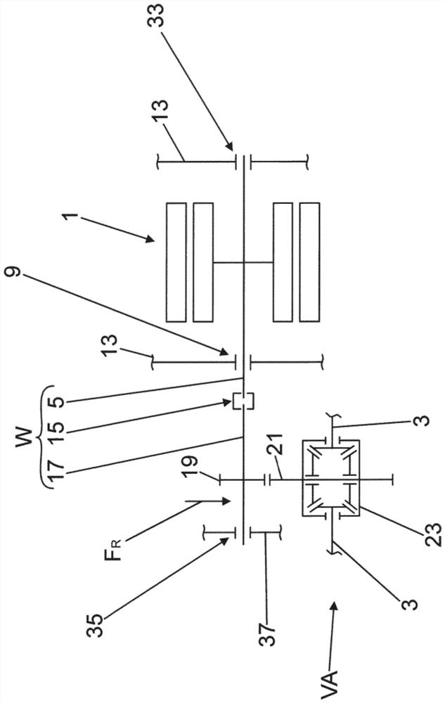
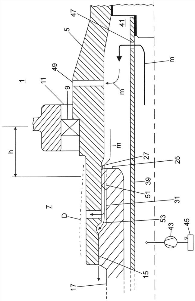
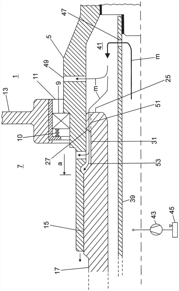
[0023] exist figure 1 A drive is shown, by means of which the front axle VA of a two-track vehicle can be driven. The front axle VA has an electric motor 1 arranged axially parallel to a flanged shaft 3 which leads to the wheels of the vehicle. The rotor shaft 5 of the motor 1 passes through the transmission 7 ( image 3 ) is connected to the two flange shafts 3 for transmission. Rotor shaft 5 - connect the rotor shaft rotating bearing 9 ( figure 1 or image 3 ) - is led out from the bearing opening 11 of the motor housing 13 and is connected to the coaxially arranged transmission drive shaft 17 via a torque-transmitting mating tooth 15 . A fixed gear 19 of the gear stage St1 of the transmission 7 is arranged on the transmission drive shaft 17 and meshes with a gear 21 on the input side of the axle differential 23 . Axle differentials 23 are driven on both sides to flanged axles 3 which lead to the wheels of the vehicle.

[0024] For the purpose of simply understanding t...


PUM


Abstract

The invention relates to a drive device for a vehicle, comprising an electric machine (1), the rotor shaft (5) of which is designed as a hollow shaft with internal toothing, into which a transmission drive shaft (17), which has external toothing (16) and is coaxial with the hollow shaft, is inserted, in particular for forming a torque-transmitting mating toothing (15), according to the invention, the rotor shaft (5) is guided outwards through a bearing opening (11) of the motor housing (13) with the intermediate connection of the rotor shaft rolling bearing (9), and the transmission drive shaft (17) has a centering seat (27) which lies in a tight clearance fit with the inner circumference of the rotor shaft (5) and bends (D) the transmission drive shaft (17) as a result of a radially acting operating force (FR) during the driving operation. According to the invention, in order to reduce the bending stresses (D), the centering seat (27) of the transmission drive shaft (17) is arranged so as to be axially aligned with the rotor shaft rolling bearing (9) without axial misalignment with respect to the rotor shaft rolling bearing (9).

Description

technical field [0001] The invention relates to a drive for a vehicle according to the preamble of claim 1 and a method for manufacturing a transmission drive shaft in such a drive according to claim 8 . Background technique [0002] In an electrically operated dual track vehicle, for example, the electrically driven front axle can have an electric machine. If necessary, the electric motor can be arranged parallel to the flange shaft axis leading to the vehicle wheels. In this case, the electric machine can be driven via a single-acting or double-acting spur gear transmission stage to the front axle differential and on to the vehicle front axle flange shaft which leads to the vehicle wheels. [0003] In this type of drive, the rotor shaft of the electric machine is designed as a hollow shaft with internal toothing, into which a transmission drive shaft with external toothing coaxial to the hollow shaft is inserted, in particular for forming the transmission Momentary matin...

Claims


Application Information

Patent Timeline
Patent Type & Authority Applications(China)
IPC IPC(8): F16H57/04
CPCF16H57/043F16D1/101F16D2001/103F16D2300/06F16H2057/02034B60K1/00
Inventor M·舍费尔M·卢克斯
Owner AUDI AG
Why Eureka
Try Eureka