Milling cutter assembly for precision machining

A technology of precision machining and milling cutters, applied in milling cutters, metal processing equipment, milling machine equipment, etc., can solve the problems of low work efficiency, time-consuming, time-consuming and labor-intensive, and achieve the effect of fast switching, simple and easy operation.

Pending Publication Date: 2022-07-12
常州博胜天泓工具有限公司
View PDF10 Cites 1 Cited by
  • Summary
  • Abstract
  • Description
  • Claims
  • Application Information

AI Technical Summary

Problems solved by technology

[0003] When the existing milling cutter is performing precision machining, it is necessary to frequently replace the milling cutter for workpieces with different hardness so that it can meet the processing needs. The existing milling cutter replacement process is time-consuming and

Method used


Image

  • Milling cutter assembly for precision machining
  • Milling cutter assembly for precision machining
  • Milling cutter assembly for precision machining

Examples


Example Embodiment

[0031] In order to make the purposes, technical solutions and advantages of the embodiments of the present invention clearer, the technical solutions in the embodiments of the present invention will be clearly and completely described below with reference to the accompanying drawings in the embodiments of the present invention. Obviously, the described embodiments These are some embodiments of the present invention, but not all embodiments. Based on the embodiments of the present invention, all other embodiments obtained by those of ordinary skill in the art without creative efforts shall fall within the protection scope of the present invention.

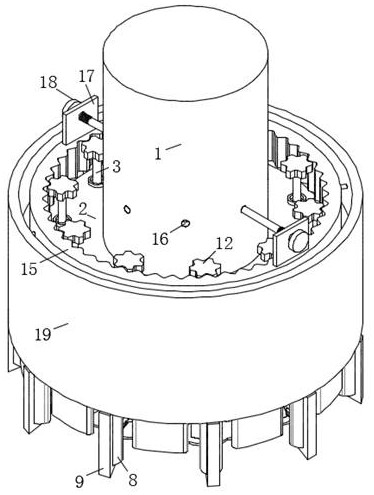
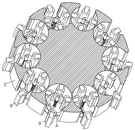
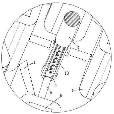
[0032] The present invention provides a milling cutter assembly for precision machining, such as Figure 1-9As shown in the figure, it includes an output shaft 1, the bottom of the output shaft 1 is fixedly connected with a circular plate 2, the interior of the circular plate 2 is equidistantly surrounded with a circular cavity, and...


PUM


Abstract

The invention relates to the technical field of machine tool machining, and particularly discloses a milling cutter assembly for precision machining. The milling cutter assembly comprises an output shaft, the bottom of the output shaft is fixedly connected with a circular plate, circular cavities are formed in the circular plate at equal intervals in a surrounding mode, openings communicated with the circular cavities are formed in the outer side of the circular plate, a rotating rod is vertically and rotationally installed in the middle of the circular cavities, sliding grooves are formed in the outer side of the rotating rod at equal intervals in a surrounding mode, and sliding blocks are slidably installed in the sliding grooves. Milling cutters with different hardness can be rapidly switched, the requirement for machining workpieces with different hardness can be met, the whole process is simple and easy to operate, time and labor are saved, a mounting frame for mounting the milling cutters can be pushed while the milling cutters are switched, the milling cutters can be pushed out of an opening, and the machining efficiency is improved. And under the condition that the first spring fails due to long-term use and cannot be normally used, normal push-out of the mounting frame can still be ensured, then normal switching is ensured, and the device is worthy of popularization and use.

Description

technical field [0001] The invention belongs to the technical field of machine tool processing, and particularly relates to a milling cutter assembly for precision machining. Background technique [0002] A milling cutter is a rotary tool with one or more teeth for milling. When working, each cutter tooth cuts off the allowance of the workpiece intermittently in turn. Milling cutters are mainly used for machining planes, steps, grooves, forming surfaces and cutting workpieces on milling machines, and for machining planes on horizontal milling machines. The cutter teeth are distributed on the circumference of the milling cutter, and are divided into straight teeth and helical teeth according to the tooth shape. According to the number of teeth, there are two kinds of coarse teeth and fine teeth. The helical-tooth coarse-tooth milling cutter has few teeth, high tooth strength, and large chip space, which is suitable for rough machining; fine-toothed milling cutter is suitab...

Claims


Application Information

Patent Timeline
IPC IPC(8): B23C5/06B23C5/24
CPCB23C5/06B23C5/24
Inventor 毛文斌
Owner 常州博胜天泓工具有限公司
Why Eureka
Try Eureka