
Patsnap Eureka
For R&D, Patsnap Eureka makes reading and utilizing patents & technical documents easy.
Patsnap Eureka AIR
Designed for self-driven R&D workflows. Generate viable solutions, solve complex R&D challenges, empower your innovation with AI.

Patsnap Eureka Materials
Designed for material experts only. Revolutionize your material R&D, from search, analyze, to developing new materials.

TechResearch
Generate reliable direction feasibility study reports for your R&D in just a few steps.

TechSeek
Discover and master advanced knowledge NOW. Basics, ideas, possibilities, all at once.

TechMind
As an expert in R&D Theories, TechMind can generates customized viable solutions instantly.

TechRisk
Analyze your overall solution with one click, know your potential R&D risks in advance.

TechMonitor
Get weekly tech updates, stay abreast of the latest tech innovations and key insights.
Carrier cable clamp feeding device, system and method for catenary dropper installation construction
A technology of feeding device and catenary cable, applied in the direction of overhead lines, manufacturing tools, hand-held tools, etc., can solve the problems of high risk and low efficiency, and achieve the effect of improving operation efficiency and reducing the risk of manual operation
- Summary
- Abstract
- Description
- Claims
- Application Information
AI Technical Summary
Problems solved by technology
Method used
Image

Examples
Embodiment 1
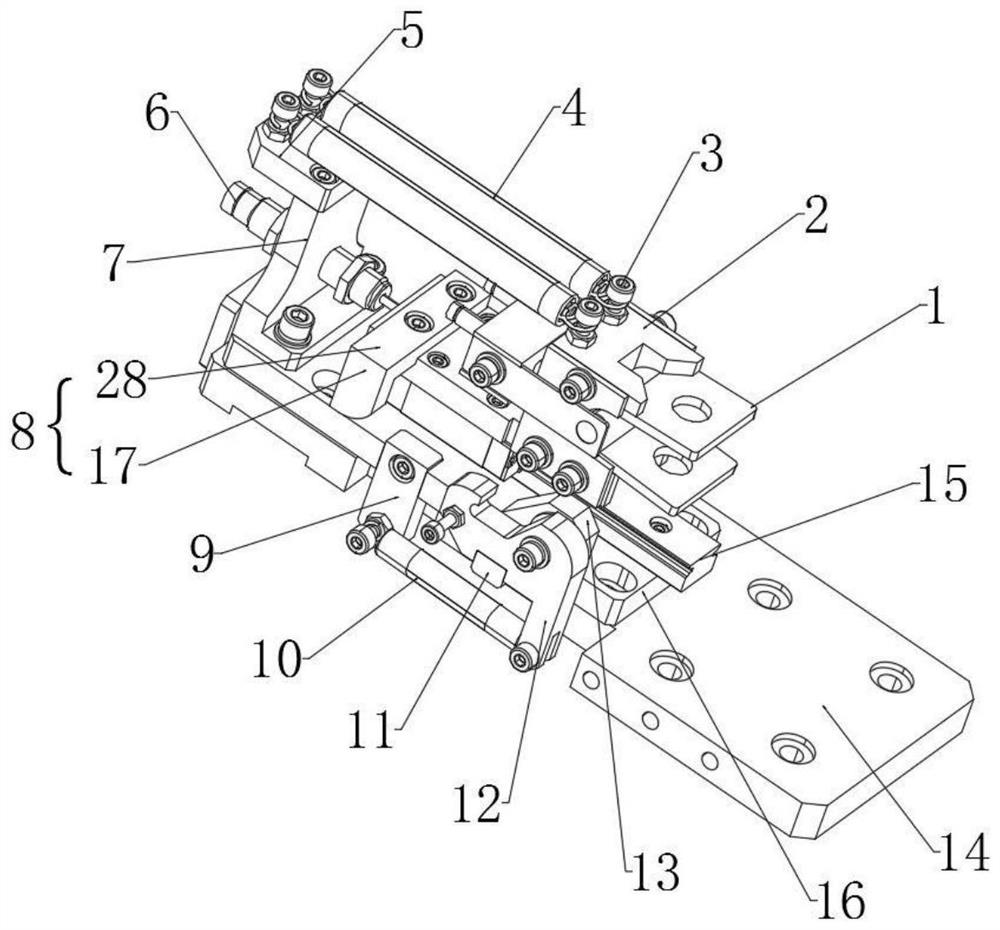
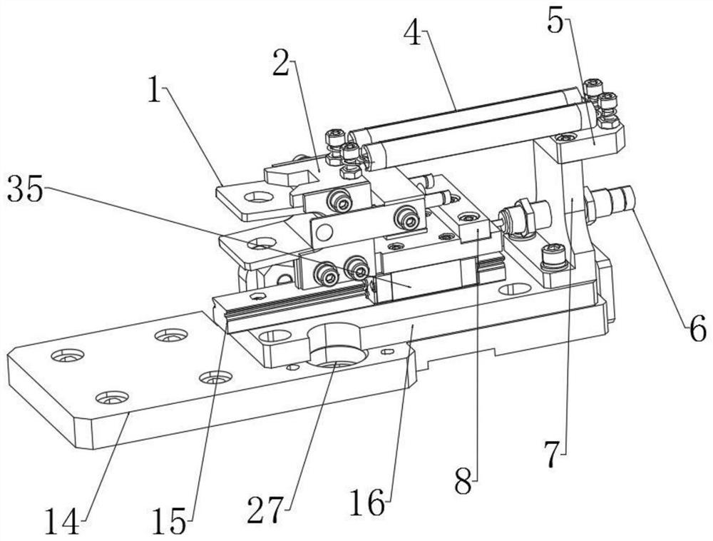
[0030] see Figure 1 to Figure 9 , the catenary chord installation and construction use the bearing cable U-shaped clip feeding device, the feeding device includes a clamping mechanism, a feeding mechanism and a displacement monitoring component 6 for measuring the feeding amount of the bearing cable U-shaped clip 1 , the clamping mechanism includes a connecting seat 2, the connecting seat 2 is fixedly provided with a clamping assembly for pressing the bottom of the U-shaped clip 1 of the bearing cable to the connecting seat 2, and the feeding mechanism includes a feeding table 16, The connecting base 2 is slidably arranged on the feeding table 16 .
[0031] The feeding system of the U-shaped wire clip of the bearing cable for the installation and construction of the catenary hanging string is provided, and the feeding system includes the above-mentioned feeding device and a manipulator for controlling the feeding system. The parts that need to be moved in the feeding device ...
Embodiment 2
[0039] Embodiment 2 is an improvement on the basis of Embodiment 1: the clamping mechanism further includes a first connecting plate 8, the first connecting plate 8 is L-shaped, and the first connecting plate 8 includes an integrally connected matching plate 17 and The second fixing plate 28, the second fixing plate 28 is fixedly connected with the connecting seat 2, and the feeding table 16 is provided with a matching plate 17 to limit the feeding position of the U-shaped clip 1 of the load-bearing cable. locking mechanism.
[0040] The mating plate 17 is a rectangular plate with one rounded corner.
Embodiment 3
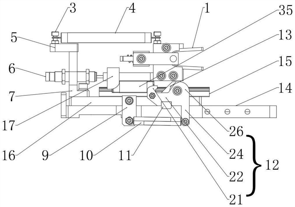
[0042] Embodiment 3 is an improvement on the basis of Embodiment 2: the locking mechanism includes a limit plate 13 fixed on the feeding table 16, and the limit plate 13 is used to prevent the matching plate 17 from moving , the limiting plate 13 is rotatably connected with a locking plate 12 matched with the matching plate 17 , the feeding table 16 is fixedly connected with a fixing block 9 , and a second spring 10 is connected between the locking plate 12 and the fixing block 9 .
[0043]The fixing block 9 is fixedly connected with the feeding table 16 through the third bolt 20, the second bolt 19 and the fourth bolt 23 are respectively pierced on the fixing block 9 and the locking plate 12, and both ends of the second spring 10 are fixedly connected with The hook, the two ends of the hook are respectively arranged on the second bolt 19 and the fourth bolt 23 . The locking plate 12 is fixedly connected with the limiting block 11 , a limiting groove is defined on the bottom s...
PUM
 Abstract
Description
Claims
Application Information
 - R&D Engineer
- R&D Manager
- IP Professional
- Industry Leading Data Capabilities
- Powerful AI technology
- Patent DNA Extraction
Browse by: Latest US Patents, China's latest patents, Technical Efficacy Thesaurus, Application Domain, Technology Topic, Popular Technical Reports.
© 2024 PatSnap. All rights reserved.Legal|Privacy policy|Modern Slavery Act Transparency Statement|Sitemap|About US| Contact US: help@patsnap.com