Novel rotating shaft sealing device

A technology of sealing device and rotating shaft, applied in the direction of engine seal, transmission parts, belt/chain/gear, etc., can solve the problems of shortening the service life of the rotary seal, affecting the working performance of the transmission device, and reducing the life of the lip seal, etc. Achieve the effect of maintaining continuous sealing ability, improving flexibility and flexibility, and improving sealing performance

Pending Publication Date: 2022-07-12
TIANJIN UNIVERSITY OF SCIENCE AND TECHNOLOGY
View PDF0 Cites 0 Cited by
  • Summary
  • Abstract
  • Description
  • Claims
  • Application Information

AI Technical Summary

Problems solved by technology

[0002] The transmission is a transmission device of mechanical equipment. The input shaft of the transmission device is supported by rolling bearings. The bearing seal at the extended end of the input shaft is a rotary seal, which mainly realizes the seal between the rotating shaft and the bearing cover to prevent the lubricating oil of the bearing from leaking outside. The dynamic characteristics and running accuracy of rolling bearings play an important role. The rotary seal often adopts a skeleton structure with a spring snap ring. The spring snap ring provides a c

Method used


Image

  • Novel rotating shaft sealing device

Examples


Embodiment Construction

[0021] The implementation of the present invention is further described with reference to the accompanying drawings.

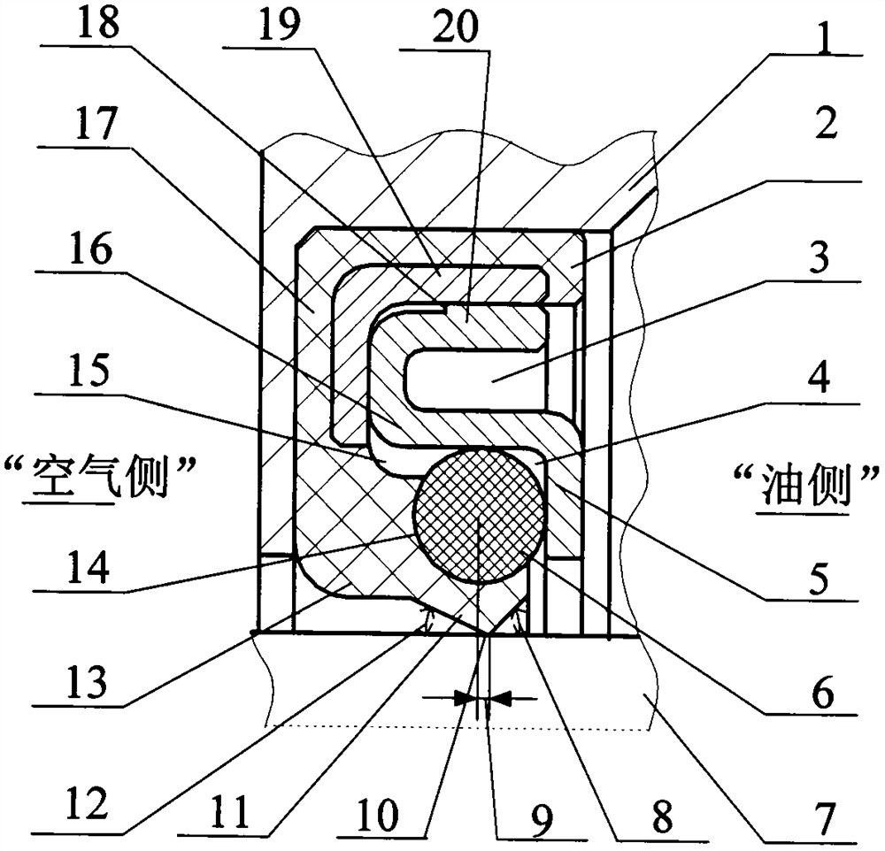
[0022] A new type of rotary shaft sealing device, the sealing device is used to seal the gap between the rotary shaft 7 and the bearing cover 1, including a lip seal 17 sleeved in the bearing cover cavity, an elastic force compensation O-ring 6, an adapter ring 16 , the lip seal 17 is composed of a lip 11, a supporting part 13, an external glue part 2 and an "L-shaped" exposed metal skeleton 19 to form a "C-shaped" cavity 15, and the lip 11 is in contact with the rotating shaft 7. There is a lip tip 10, a semicircular groove 14 is formed on the outer upper edge, the left and right sides of the lip tip 10 are respectively made with an air measuring lip angle 12 and an oil side lip angle 8, the elastic compensation O-ring 6 is made of rubber. The adapter ring 16 is composed of the upper support section 20 and the lower pressure section 5, and the cross-sectional...


PUM

PropertyMeasurementUnit
Thicknessaaaaaaaaaa
Heightaaaaaaaaaa

Abstract

The invention provides a novel rotating shaft sealing device which comprises a lip-shaped seal, an elastic force compensation O-shaped ring and an adaptive ring which are sleeved in a bearing cover cavity, the lip-shaped seal is composed of a lip part, a supporting part, an outer gluing part and an L-shaped exposed metal framework, a C-shaped cavity is formed, a lip tip is arranged at the contact position of the lip part and a rotating shaft, and the elastic force compensation O-shaped ring is arranged on the lip tip. A semi-circular groove is formed in the outer upper edge, an air side lip corner and an oil side lip corner are arranged on the left side and the right side of the lip tip respectively, the elastic compensation O-shaped ring is made of rubber materials and sleeved with the semi-circular groove, the adaptive ring is composed of an upper supporting section and a lower pressurizing section, the profile of the section of the adaptive ring is in an S shape, and a U-shaped deformation cavity and a semi-closed pressurizing cavity are formed. A tiny protrusion is arranged on the upper edge of the outer portion of the upper supporting section and pressed into a C-shaped cavity of the lip-shaped seal, the lower pressurizing section presses and seals the elastic compensation O-shaped ring, and the elastic compensation O-shaped ring is wide in application range, good in sealing flexibility, high in dynamic eccentricity compensation capacity, small in friction torque, good in sealing performance and long in service life.

Description

technical field [0001] The invention relates to a bearing seal of a transmission input shaft of a mechanical equipment, in particular to a novel rotary shaft seal device. Background technique [0002] The transmission is the transmission device of mechanical equipment. The input shaft of the transmission device is supported by rolling bearings. The bearing seal on the overhanging end of the input shaft is a rotary seal. The dynamic characteristics and running accuracy of rolling bearings play an important role. The rotating seal often adopts a skeleton structure with a spring snap ring. The spring snap ring provides a constant radial force to ensure a high contact pressure between the rotating seal and the rotating shaft and prevent leakage. , When the shaft rotates at high speed, the higher contact pressure increases the friction torque, there is a danger of excessive wear and thermal load increase, and the service life of the rotary seal is shortened, especially when the i...

Claims


Application Information

Patent Timeline
IPC IPC(8): F16H57/029F16J15/32F16J15/3208F16J15/3216F16J15/3224F16J15/3252F16J15/3268
CPCF16H57/029F16J15/32F16J15/3216F16J15/3224F16J15/3208F16J15/3252F16J15/3268
Inventor 张付英杨朋伟吴继豪
Owner TIANJIN UNIVERSITY OF SCIENCE AND TECHNOLOGY
Why Eureka
Try Eureka