Focusing device for space deep hypothermia optical remote sensing instrument

An optical remote sensing and deep low temperature technology, applied in the field of space remote sensing, can solve the problems of reducing the overall weight and space, poor vibration resistance, low stiffness of the focusing device, etc., and achieve the effect of reducing the overall weight and space, and not easy to jam

Pending Publication Date: 2022-07-12
SHANGHAI INST OF TECHNICAL PHYSICS - CHINESE ACAD OF SCI
View PDF9 Cites 0 Cited by
  • Summary
  • Abstract
  • Description
  • Claims
  • Application Information

AI Technical Summary

Problems solved by technology

[0005] In order to overcome the low rigidity of the above-mentioned focusing device, the large frequency response, poor vibration resistance and the situation that the screw thread engagement is likely to be jammed due to the increased friction caused by the above-mentioned torque during the focusing process, the purpose of the present invention is to Provided is a focusing device for deep and low temperature optical remote sensing instruments in space. The torque generated by the friction force and the gravity of the focusing mirror chamber itself will not cause the angle change of the focusing mirror chamber, and the matching surface will not change during the focusing process. The operation is always uniform and stable, not prone to jamming, and reduces the overall weight and space

Method used


Image

  • Focusing device for space deep hypothermia optical remote sensing instrument
  • Focusing device for space deep hypothermia optical remote sensing instrument
  • Focusing device for space deep hypothermia optical remote sensing instrument

Examples


Embodiment Construction

[0021] The technical solutions of the present invention are further described below with reference to the accompanying drawings and through specific embodiments.

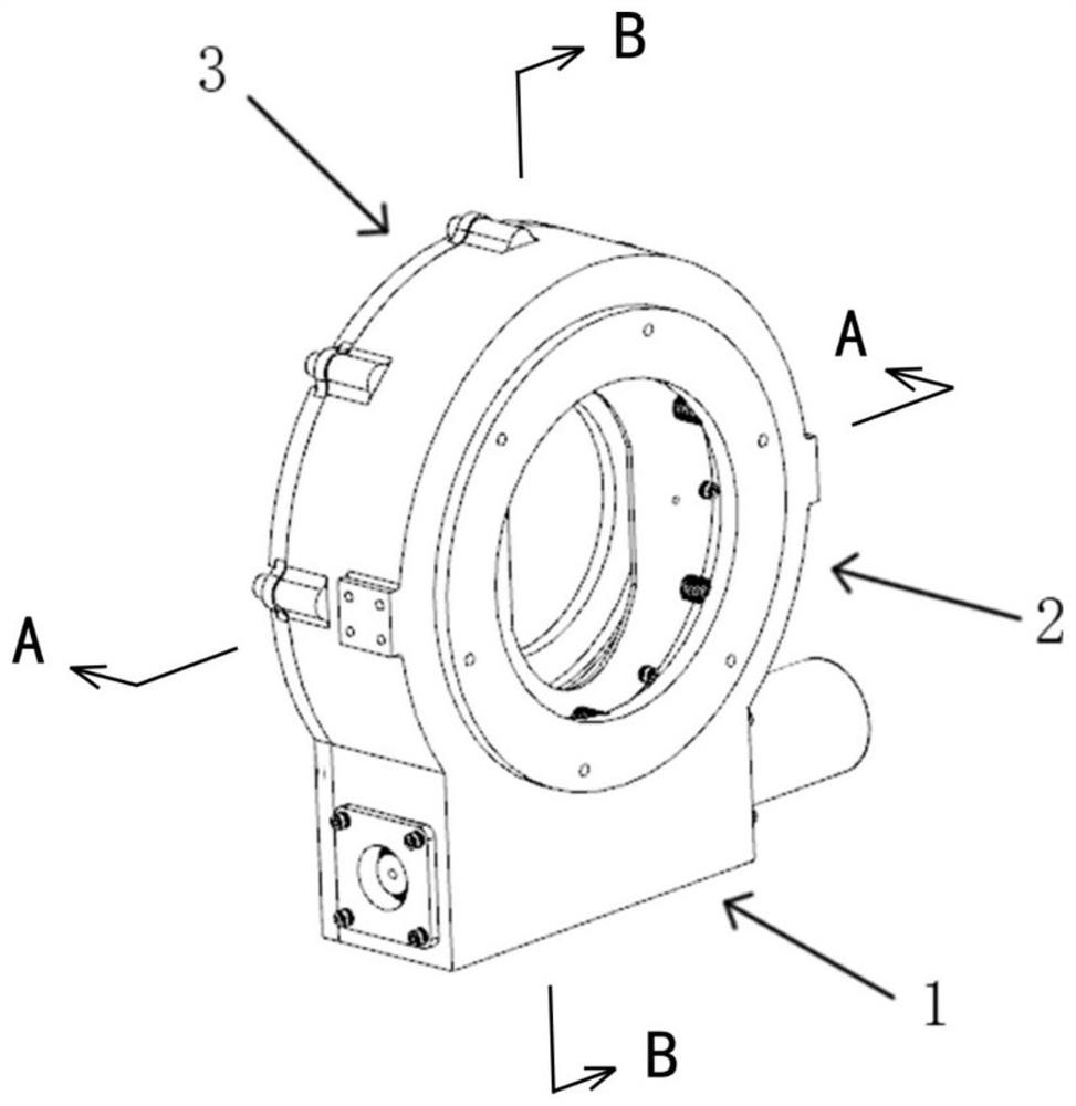
[0022] figure 1 A focusing device for a space deep and low temperature optical remote sensing instrument according to a preferred embodiment of the present invention is shown, which mainly includes: a power drive assembly 1 , a focusing drive assembly 2 and a casing 3 . The power drive assembly 1 is drivingly connected to the focus drive assembly 2 .

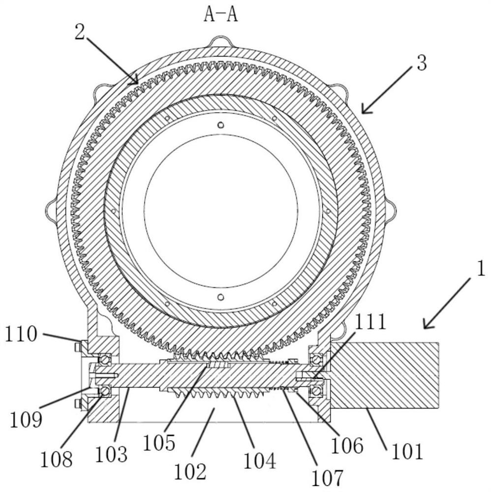
[0023] like figure 2 As shown, the power drive assembly 1 mainly includes a motor 101 and a worm 102 that provide driving force. The motor 102 is connected to the worm 102 via, for example, a motor key 111 . The worm 102 includes a worm shaft 103 and a worm gear sleeve 104 sleeved in the middle of the worm shaft 103 . The worm gear sleeve 104 is connected with the worm shaft 103 through the worm gear sleeve key 105 . It should be understood that the worm gear sl...


PUM


Abstract

The invention provides a focusing device for a space deep hypothermia optical remote sensing instrument, which comprises a power driving assembly, a focusing driving assembly and a shell, and is characterized in that the power driving assembly is connected to the focusing driving assembly in a driving manner, the power driving assembly comprises a motor for providing driving force and a worm connected with the motor, and the worm is connected with the power driving assembly; the focusing driving assembly comprises a worm gear and a focusing lens chamber, worm gear teeth are arranged on the outer ring of the worm gear, the worm is meshed with the worm gear, and the worm gear is connected to the focusing lens chamber in a driving mode so as to drive the focusing lens chamber to move axially to achieve focusing. Through the arrangement of the focusing device, the operation of the matching surface in the focusing process can be kept uniform and stable all the time, jamming is not easy to occur, and the overall weight and space are reduced.

Description

technical field [0001] The present invention relates generally to space remote sensing technology, and particularly to space optical remote sensing instruments. Background technique [0002] As we all know, the transmission optical system generally needs a focusing device. At present, there are roughly two types of focusing devices for transmissive optical systems: one is a focusing device that adjusts the position of the focal plane of the detector. No matter what kind of transmission method is used, this type of focusing device is difficult to integrate with a compact and tightly sealed device. The Dewar structure is compatible, so it is not suitable for extremely low temperature conditions such as space; the second is the focusing device for adjusting the position of the focusing mirror, which is currently mostly driven by a lead screw and guided by a linear bearing. [0003] CN102565997A discloses the second solution as mentioned above, which converts the rotational mot...

Claims


Application Information

Patent Timeline
Patent Type & Authority Applications(China)
IPC IPC(8): G02B7/04
CPCG02B7/04
Inventor 陈凡胜张恒孙小进张勇
Owner SHANGHAI INST OF TECHNICAL PHYSICS - CHINESE ACAD OF SCI
Why Eureka
Try Eureka