Detachable multifunctional mobile power distribution cabinet

A multi-functional, power distribution cabinet technology, applied in the substation/power distribution device shell, electrical components, substation/switch layout details, etc., can solve the problems of multi-manpower, non-movable, troublesome, etc., to expand the installation position and facilitate disassembly Separate inspection and easy installation

Active Publication Date: 2022-07-12
国网冀北电力有限公司超高压分公司
View PDF7 Cites 0 Cited by
  • Summary
  • Abstract
  • Description
  • Claims
  • Application Information

AI Technical Summary

Problems solved by technology

[0003]1. Most of the existing power distribution cabinets are integrated power distribution cabinets installed on the ground. It will penetrate into the power distribution cabinet, causing the electrical components inside the power distribution cabinet to be wetted;
[0004]2. In the existing power distribution cabinet, most of the electrical components are installed on the inner wall of the power distribution cabinet, which leads to limited space for installing the meter inside the power distribution cabinet, and cannot For disassembly and maintenance, it is necessary to manually enter the interior of the power distribution cabinet for maintenance, which is troublesome;
[0005]3. Most of the existing power distribution cabinets are fixed and cannot be moved. When the power distribution cabinet needs to be moved as a whole, a crane is required. Large tools require more manpower to cooperate, which is more troublesome;
[0006]4. A large number of electric meters and other electrical components will be installed in the existing power distribution cabinet, but the existing power distribution cabinet cannot realize remote meter reading, and manual meter reading is required Checking is more troublesome. Therefore, a detachable multifunctional mobile power distribution cabinet is proposed

Method used


Image

  • Detachable multifunctional mobile power distribution cabinet
  • Detachable multifunctional mobile power distribution cabinet
  • Detachable multifunctional mobile power distribution cabinet

Examples


Embodiment Construction

[0051] The technical solutions in the embodiments of the present invention will be clearly and completely described below with reference to the accompanying drawings in the embodiments of the present invention. Obviously, the described embodiments are only a part of the embodiments of the present invention, rather than all the embodiments. Based on the embodiments of the present invention, all other embodiments obtained by those of ordinary skill in the art without creative efforts shall fall within the protection scope of the present invention.

[0052] see Figure 1-Figure 18 , the present invention provides a kind of technical scheme:

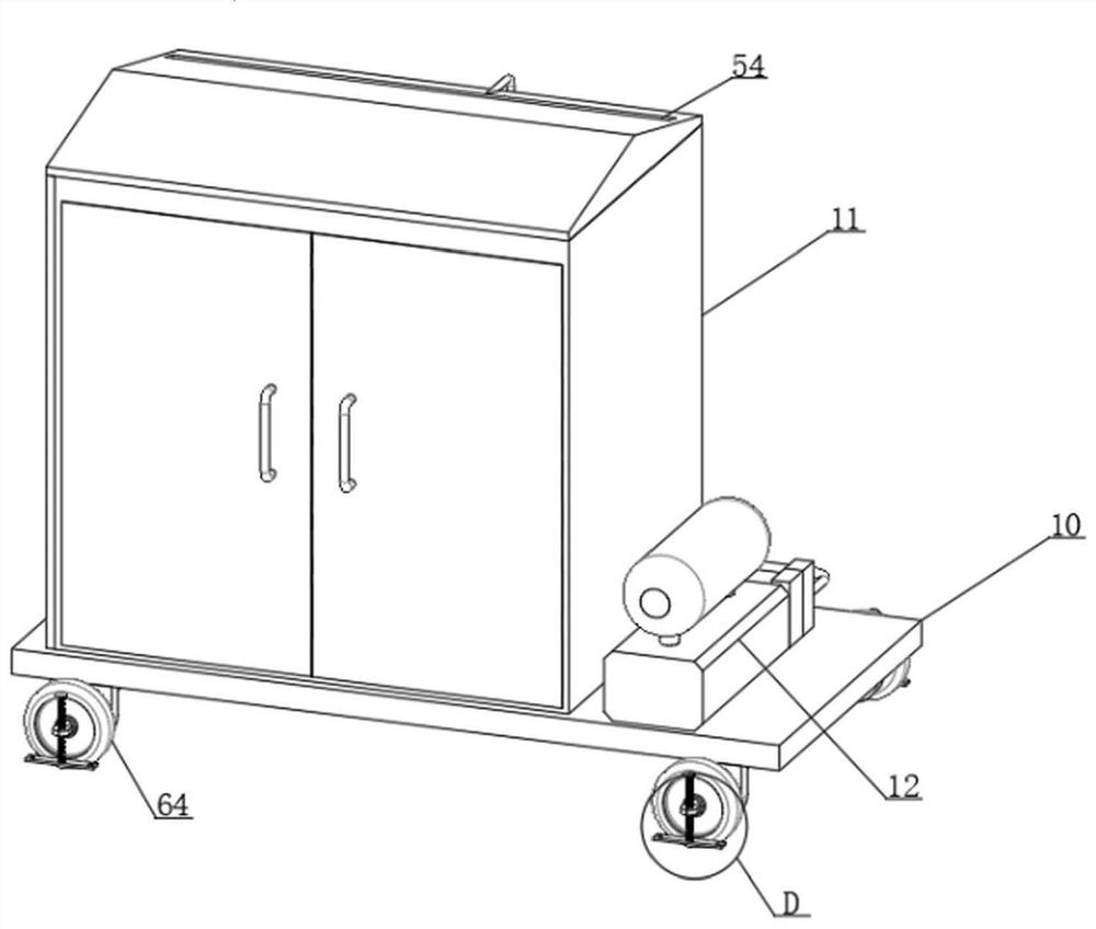
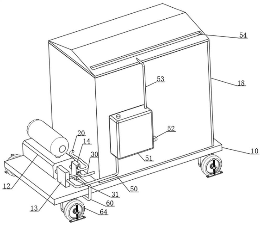
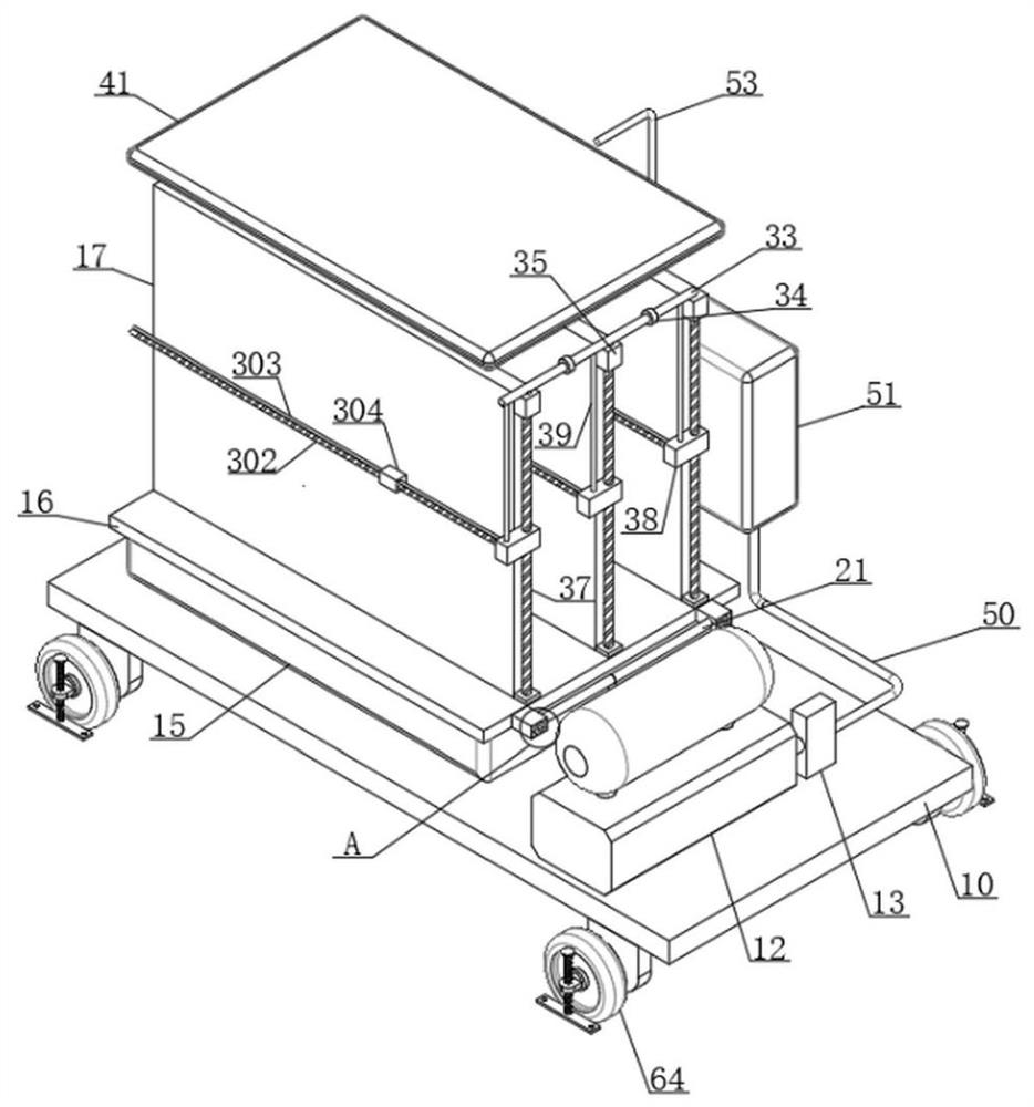
[0053] A detachable multifunctional mobile power distribution cabinet, comprising: a mobile bearing plate 10, a cabinet body 11 is fixedly installed on the mobile bearing plate 10, a support air bag 15 is fixedly installed inside the cabinet body 11, and the support air bag 15 is fixedly installed There is a support plate 16, a suction inte...


PUM


Abstract

The invention discloses a detachable multifunctional mobile power distribution cabinet, which comprises a mobile bearing plate, a cabinet body is fixedly mounted on the mobile bearing plate, a supporting air bag is fixedly mounted in the cabinet body, a supporting plate is fixedly mounted on the supporting air bag, a suction integrated pump is fixedly mounted on the mobile bearing plate, and the suction integrated pump is fixedly mounted on the cabinet body. An air inlet of the suction integrated pump is communicated with an air suction shunting box, an air outlet of the suction integrated pump is communicated with an air inlet shunting box, the position of the supporting plate can be lifted after the air bag is inflated, so that water flow is prevented from making contact with electrical components, the wetting phenomenon is avoided, meanwhile, due to the arrangement of the supporting air bag, vibration caused by the outside can be reduced, and the service life of the electrical components is prolonged. And a fourth mounting box is movably connected to the outer portion of a connecting rod, a fifth turbine fan is fixedly mounted on the outer portion of the connecting rod, the end, away from the air inlet flow dividing box, of a fourth pipe body communicates with the fourth mounting box, and an auxiliary supporting structure is mounted on the outer portion of a roller.

Description

technical field [0001] The invention relates to the technical field of power distribution cabinets, in particular to a detachable multifunctional mobile power distribution cabinet. Background technique [0002] Power distribution cabinets can be divided into power distribution cabinets, lighting distribution cabinets, metering cabinets and other power distribution system final equipment, mainly used in power plants, substations, petrochemicals, metallurgical steel rolling, light industry and textiles, factories and mining enterprises and residential quarters , high-rise buildings and other different occasions. [0003] 1. Most of the existing power distribution cabinets are one-piece power distribution cabinets, which are installed on the ground. When it rains, when the rainwater accumulates to a certain position, the rainwater will seep into the power distribution cabinet, causing the electrical components inside the power distribution cabinet to be damp. wetting phenomeno...

Claims


Application Information

Patent Timeline
Patent Type & Authority Applications(China)
IPC IPC(8): H02B1/54H02B1/34H02B1/56H02B1/28H02B1/30H02B1/32H02B1/52A62C3/16A62C37/00
CPCH02B1/54H02B1/34H02B1/565H02B1/28H02B1/30H02B1/32H02B1/52A62C3/16A62C37/00Y02A30/14
Inventor 于珍珠
Owner 国网冀北电力有限公司超高压分公司
Why Eureka
Try Eureka