Gas particulate matter removal method

A particle removal technology, applied in separation methods, chemical instruments and methods, cleaning methods and utensils, etc., can solve the problems of wasteful removal of particles, easy re-contamination of particles, secondary pollution, etc., to avoid tilting or Dumping, reducing energy consumption, slowing down the effect of flow

Pending Publication Date: 2022-07-15
李卓洲
View PDF0 Cites 0 Cited by
  • Summary
  • Abstract
  • Description
  • Claims
  • Application Information

AI Technical Summary

Problems solved by technology

[0005] Aiming at the deficiencies of the prior art, the present invention provides a method for removing gas particles, which solves the problem that existing gas particle removal devices are prone to residues on the surface of components inside the equipment during use, causing the gas to be removed when the particles are removed. It is easy to cause secondary pollution, and the gas is easy to be contaminated with particles again after the removal of particles, which leads to the problem of wasteful removal of particles

Method used


Image

  • Gas particulate matter removal method
  • Gas particulate matter removal method
  • Gas particulate matter removal method

Examples


Embodiment 1

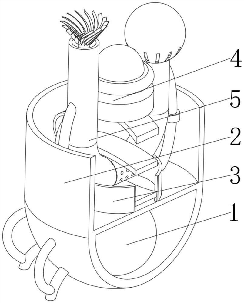
[0040] see Figure 1-6 , the present invention provides a technical solution: a gas particulate removal device, which specifically includes:

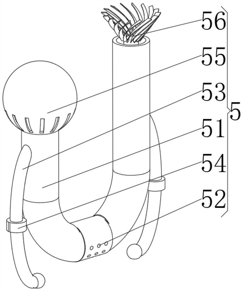
[0041] Base 1, the base 1 has a hemispherical body, a water-soluble tank 2 installed on the top of the hemispherical body, a protective device 3 installed at the bottom of the inner cavity of the water-soluble tank 2, and an adjustment device 4 installed on the top of the protective device 3. The separation device 5 on the inner surface of the protective device 3, the separation device 5 includes:

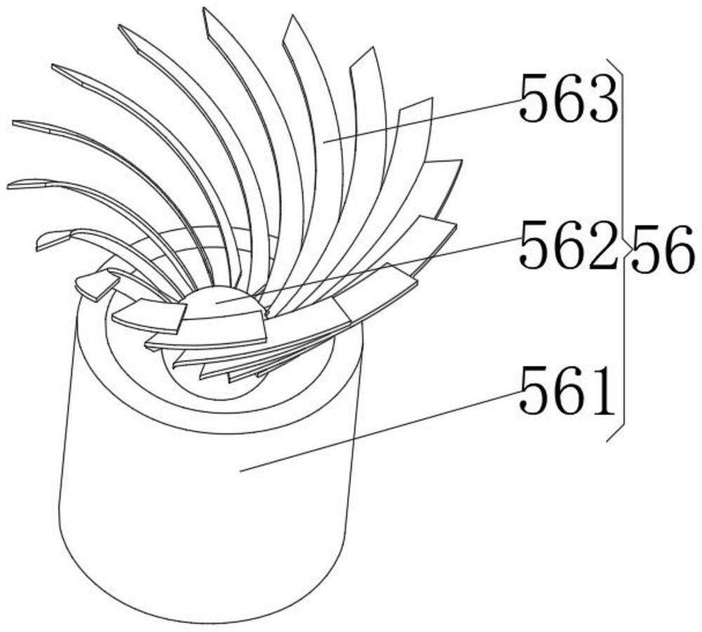
[0042] The removal pipe 51 has a U-shaped pipe body, a precipitation hole 52 opened in the middle of the bottom of the U-shaped pipe body, and an arc-shaped guide pipe 53 installed on both sides of the outer surface of the U-shaped pipe body, and A small water pump 54 installed in the middle of the arc-shaped diversion pipe 53, a spherical aspirator 55 installed at the low end of the U-shaped pipe body, and an air seal device 56 installed a...

Embodiment 2

[0052] see Figure 1-6 , on the basis of Embodiment 1, the present invention provides a technical solution: a method for removing gas particulate matter, comprising the following steps:

[0053] Step 1: inject clean water into the inner cavity of the water soluble tank 2 until the protective device 3 is submerged, and store the initial electric energy inside the center of gravity energy storage ball 12 in the base 1;

[0054] Step 2: Start the spherical aspirator 55 through the electric energy inside the center of gravity energy storage ball 12 to absorb the outside air, and start the small water pump 54 at the same time, so that the clean water in the water-soluble tank 2 is injected into the inside of the removal pipe 51;

[0055] Step 3: Start the rotating motor 43 to make the friction hemisphere 44 rotate, drive the spherical aspirator 55 to rotate through friction, carry out full-scale air suction, and inject the air into the water flow and countercurrent flushing of the ...


PUM


Abstract

The invention discloses a gas particulate matter removal device which specifically comprises a base, a protection device installed at the bottom of an inner cavity of a water-soluble box, an adjusting device installed at the top of the protection device and a separation device installed on the inner surface of the protection device. The device comprises a U-shaped pipe body, arc-shaped flow guide pipes installed on the two sides of the outer surface of the U-shaped pipe body, a small water pump installed in the middles of the arc-shaped flow guide pipes, a spherical air suction machine installed at the low end of the U-shaped pipe body, and an air sealing device installed at the high end of the U-shaped pipe body. Through the arrangement of the arc-shaped flow guide pipe, downstream and countercurrent flushing can be performed on gas by proper water flow, and meanwhile, the countercurrent water flow and downstream water flow are mutually impacted by the removal pipe of the U-shaped pipe body, so that a water tent is formed to cut off and precipitate particles flushed by the downstream water flow and the countercurrent water flow, and the particles are prevented from being adhered to the interior of an equipment component.

Description

technical field [0001] The invention relates to the technical field of environmental protection, in particular to a method for removing gas particulate matter. Background technique [0002] A large number of studies have shown that the high concentration of inhalable particulate matter and fine particulate matter in the atmosphere is the main cause of haze weather. Although the national functional departments have improved the control standards for particulate matter emissions in various industries, and the national annual average particle concentration level has declined, the problems faced are still severe. [0003] Existing gas particulate matter removal devices are prone to residues on the surfaces of components inside the equipment during use, resulting in secondary pollution of the gas during particle removal. Vain. SUMMARY OF THE INVENTION [0004] (1) Technical problems solved [0005] Aiming at the deficiencies of the prior art, the present invention provides a...

Claims


Application Information

Patent Timeline
Patent Type & Authority Applications(China)
IPC IPC(8): B01D47/02B01D21/02B08B15/00
CPCB01D47/02B01D21/02B08B15/00
Inventor 李卓洲
Owner 李卓洲
Why Eureka
Try Eureka