Dismounting tool for hot-rolling shear blade knife rest clamping cylinder

A technology for disassembling tooling and clamping cylinders, applied in the field of rolling machinery, can solve the problems of low disassembly efficiency, long time consumption, and difficulty in disassembling clamping cylinders, saving maintenance and replacement time, improving efficiency, and reducing the cost of disassembling clamping cylinders. effect of difficulty

Pending Publication Date: 2022-07-15
MCC SFRE HEAVY IND EQUIP
View PDF0 Cites 0 Cited by
  • Summary
  • Abstract
  • Description
  • Claims
  • Application Information

AI Technical Summary

Problems solved by technology

[0003] The purpose of the present invention is to provide a disassembly tool for the clamping cylinder of the hot-rolled scissor blade holder, which effectively solves the problems of difficult disassembly of the existing clamping cylinder, long time consumption and low disassembly efficiency

Method used


Image

  • Dismounting tool for hot-rolling shear blade knife rest clamping cylinder

Examples


Embodiment Construction

[0015] The present invention will be described in detail below with reference to the accompanying drawings and specific embodiments.

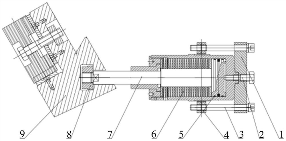
[0016] In the present invention, the clamping cylinder device of the hot-rolled shearing blade holder is disassembled, and the assembly structure is as follows: figure 1 As shown in the figure, it includes a tooling chuck 1, and a stop is formed on the bottom surface of the tooling chuck 1, and the stop is sleeved with the top wire 2.

[0017] The stop is that the tooling chuck 1 has a stepped groove to the inside around the axis. The stepped groove is clamped to the rear boss of the clamping cylinder block 4. A center hole is opened in the groove, and the center hole is sleeved to the top. Wire 2, the top wire 2 runs through the tooling chuck 1, the top wire 2 is cylindrical, the end face of the top wire 2 is set to a spherical surface, the surface of the top wire 2 is provided with an external thread, and the other end face of the top wire 2 ...


PUM


Abstract

The disassembling tool for the hot-rolling shear blade knife rest clamping cylinder comprises a tool chuck, a seam allowance is formed in the bottom face of the tool chuck, and a jackscrew is connected to the seam allowance in a sleeved mode. When the clamping cylinder is replaced and detached, movement of the piston rod is effectively controlled through the jackscrew, the pressing head and the tool rest are rapidly overlapped and separated, the cylinder body is stabilized through the effect of the tool chuck, and the piston rod is prevented from moving when the jackscrew is screwed. The device is easy to manufacture, safe, reliable, convenient to operate, capable of reducing operation difficulty, shortening operation time, convenient, fast and efficient, and capable of improving working quality. And the working efficiency is remarkably improved, and the requirements of fast-paced production and quality are met.

Description

technical field [0001] The invention belongs to the technical field of rolling machinery, and particularly relates to a disassembly tool for a clamping cylinder of a hot-rolled shearing blade holder. Background technique [0002] In today's increasing demand for strips, users' requirements for the mechanical properties of products continue to increase. When the hot rolling shears cut the strip, the clamping cylinder is responsible for clamping the shearing blade holder during the cutting process of the strip, but because the clamping cylinder in the hot rolling production line is exposed to high temperature, high dust and cooling water. High-speed and high-frequency operations are performed in harsh environments, the shearing blades are severely worn, the shearing gap becomes larger, and the shearing accuracy decreases, requiring regular disassembly and replacement. Restricted by the structure, the clamping cylinder needs to be disassembled to replace the cutting blade hold...

Claims


Application Information

Patent Timeline
Patent Type & Authority Applications(China)
IPC IPC(8): B25B27/00B25B11/00
CPCB25B27/00B25B11/00
Inventor 孙冬冬王志强柴佐华王菊
Owner MCC SFRE HEAVY IND EQUIP
Why Eureka
Try Eureka