
Containing device and heat dissipation system

A storage and storage frame technology, which is applied in substation/distribution device casing, substation/switchgear cooling/ventilation, etc., can solve the problems of fast heat dissipation of electrical parts, poor temperature uniformity, and unbalanced heat dissipation of electrical modules, etc. , to achieve the effect of balanced air flow and heat dissipation

Pending Publication Date: 2022-07-15
厦门科华数能科技有限公司
View PDF0 Cites 0 Cited by
  • Summary
  • Abstract
  • Description
  • Claims
  • Application Information

AI Technical Summary

Problems solved by technology

[0002] Electrical parts tend to generate a lot of heat after working for a period of time, especially when the density of electrical parts is relatively high, the heat generated by the electrical modules formed after the installation of electrical parts is also increasing. Most of the existing electrical parts are placed In the container-type box or cabinet, the electrical components are arranged in the vertical direction, and a backpack air conditioner is usually placed outside the box or cabinet to dissipate heat inside the box. Generally speaking, the air outlet and suction port of the backpack air conditioner Arranged at intervals up and down, this makes the electrical parts near the air exhaust outlet dissipate heat faster, while the electrical parts far away from the air exhaust outlet dissipate heat slowly, which makes the heat dissipation of the electrical module unbalanced and affects the service life of the electrical parts
Especially when the electrical component is a battery, the temperature of the battery at different positions in the box varies greatly, the temperature uniformity is poor, and the temperature difference between the front and rear ends of the battery is also likely to be inconsistent. When the system runs for a long time, it will lead to inconsistent aging of the battery and affect the overall charging of the system. Discharge performance, which poses a higher risk to system operation

Method used


Image

  • Containing device and heat dissipation system
  • Containing device and heat dissipation system
  • Containing device and heat dissipation system

Examples


Embodiment Construction

[0040] The technical solutions in the embodiments of the present invention will be clearly and completely described below with reference to the accompanying drawings in the embodiments of the present invention. Obviously, the described embodiments are preferred embodiments of the present invention and should not be construed to exclude other embodiments. Based on the embodiments of the present invention, all other embodiments obtained by those of ordinary skill in the art without creative efforts fall within the protection scope of the present invention.

[0041] In the claims, description and the above drawings of the present invention, unless otherwise clearly defined, the terms "first", "second" or "third" are used to distinguish different objects, rather than used for Describe a specific order.

[0042] In the claims, description and the above drawings of the present invention, unless otherwise expressly defined, the terms "center", "horizontal", "longitudinal", "horizont...


PUM


Abstract

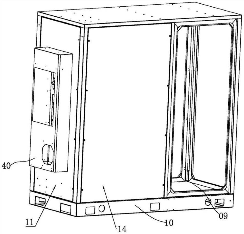
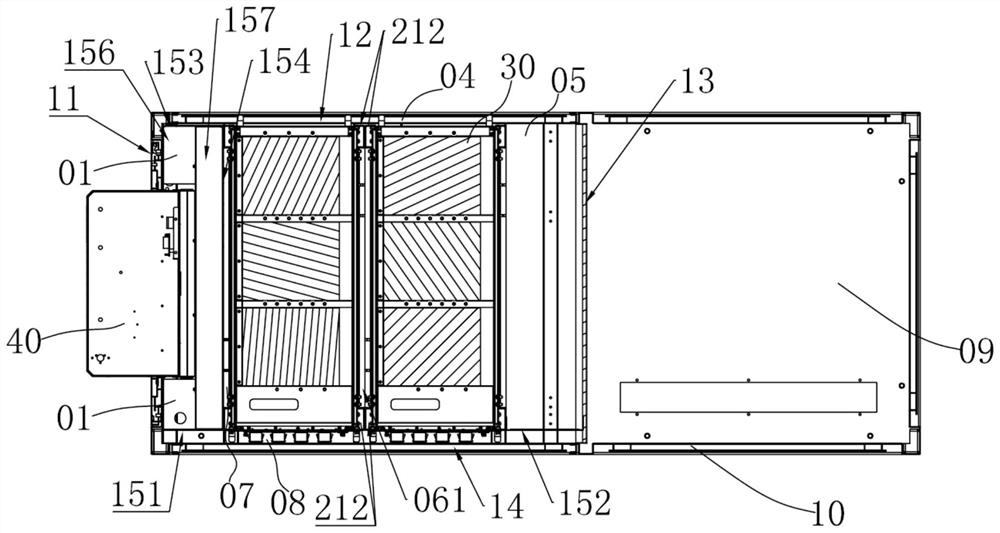
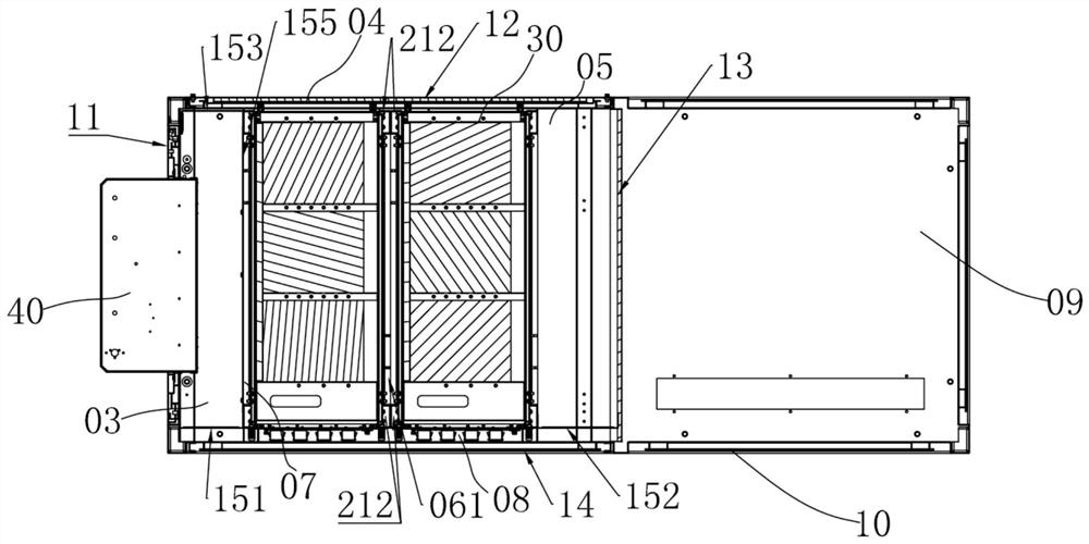
The invention discloses a containing device and a heat dissipation system, the containing device comprises a cabinet body and a containing assembly, the cabinet body is provided with a first side wall, a second side wall, a third side wall and a fourth side wall, the cabinet body is provided with an air inlet cavity, an air outlet cavity and an air passing cavity, and the air inlet cavity is provided with a first air passing opening; the air outlet cavity is provided with a second air passing opening. The accommodating assembly accommodates all the electrical parts to form an electrical module, a first air channel communicating with the first air passing opening is formed between the electrical module and the second side wall and / or the fourth side wall, a second air channel communicating with the first air channel is further formed between the electrical module and the third side wall, and the electrical module is further suitable for forming an air passing chamber with the first side wall. The air passing chamber adjoins the air inlet cavity and the air outlet cavity and communicates with the second air passing opening, and a third air channel only communicating with the second air channel and the air passing chamber is further suitable for being formed between the electrical parts of the adjacent layers. The heat dissipation system comprises the accommodating device. The containing device and the heat dissipation system are good in temperature uniformity, and the service life of electrical parts is long.

Description

technical field [0001] The invention relates to the field of heat dissipation, in particular to a accommodating device and a heat dissipation system. Background technique [0002] Electrical components are prone to generate a lot of heat after working for a period of time, especially when the density of electrical components is relatively high, the calorific value of the electrical modules formed after the electrical components are installed is also increasing, and the existing electrical components are mostly placed. In a container-type box or cabinet, the electrical components are arranged in the vertical direction. A backpack-type air conditioner is usually placed outside the box or cabinet to dissipate heat inside the box. The upper and lower intervals are arranged, which makes the electrical components close to the exhaust vents dissipate faster, while the electrical components far from the exhaust vents dissipate slowly, which makes the heat dissipation of the electric...

Claims


Application Information

Patent Timeline
IPC IPC(8): H02B1/56H02B1/30
CPCH02B1/565H02B1/30
Inventor 魏礼贵卢艺杰康志远
Owner 厦门科华数能科技有限公司
Learn More