Turbine with contra-rotating turbine for aircraft
A turbine and aircraft technology, applied in the lubrication of turbines/propulsion devices, gas turbine devices, machines/engines, etc., can solve the problems of limiting the radial integration of reduction gears, difficulty in lubricating inter-shaft bearings, complex integration solutions, etc., to achieve easy Assembly effect
Pending Publication Date: 2022-07-15
SAFRAN AIRCRAFT ENGINES SAS +1
View PDF0 Cites 0 Cited by
- Summary
- Abstract
- Description
- Claims
- Application Information
AI Technical Summary
Problems solved by technology
[0009] The architecture is complex due to its mechanical integration: the mechanical reduction gear is located downstream of the turbine, radially inside the stator casing (known as the exhaust casing)
[0010] Existing integrated solutions are particularly complex due to the presence of many inter-shaft bearings which are particularly difficult to lubricate
The radial load of the turbine is likely to pass through the gearbox holding the two shafts radially, which is extremely detrimental to the good performance of the reduction unit
Finally, the space requirements are not optimized, especially in the presence of bearings below the planetary or sun gears of the reduction unit, which limits the radial integration of the reduction unit
Method used
View moreImage
Smart ImageViewing Examples

Examples
Embodiment Construction
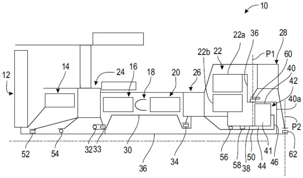
[0046] figure 1 A turbine 10 with a counter-rotating turbine for an aircraft is shown in a very schematic manner.
[0047] The turbine 10 includes a fan 12 , a low pressure compressor 14 , a high pressure compressor 16 , an annular combustor 18 , a high pressure turbine 20 and a counter-rotating turbine 22 from upstream to downstream in the direction of gas flow.
Login to view more PUM
 Abstract
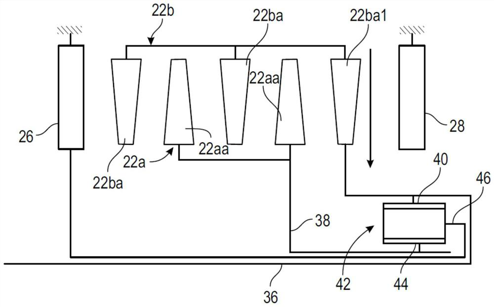
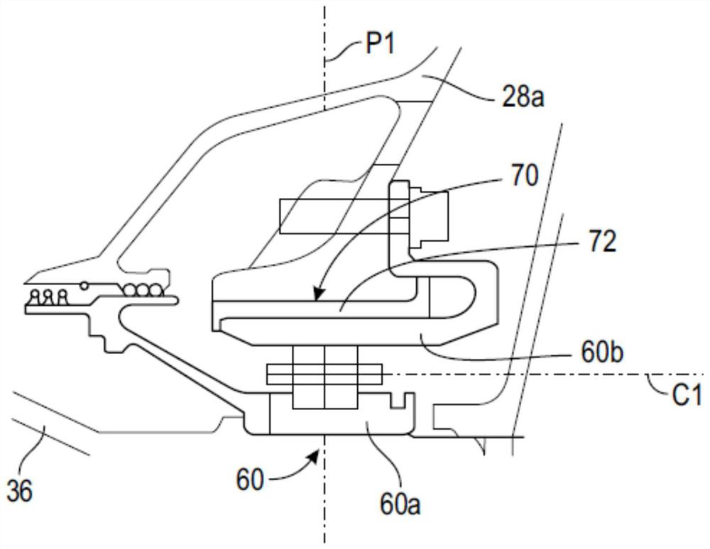
A turbine (10) with a counter rotating turbine for an aircraft, the turbine comprising a counter rotating turbine (22), a first rotor (22a) of the counter rotating turbine being configured to rotate in a first direction of rotation and connected to a first turbine shaft (36), a second rotor (22b) of the counter rotating turbine being configured to rotate in an opposite direction of rotation and connected to a second turbine shaft (38), the first rotor comprises turbine discs staggered between turbine discs of the second rotor, said first shaft (36) being guided by at least two guide bearings (60, 62) mounted between the first shaft and the stator housing, and said second shaft (38) being guided by at least two guide bearings (56, 58) mounted between the second shaft and the other stator housing (28).
Description
technical field [0001] The present invention relates to a turbine with a counter-rotating turbine for an aircraft. Background technique [0002] In particular, the prior art includes documents US-A1-2019 / 085701, EP-A1-3 447 243, EP-A1-2 975213 and WO-A1-2013 / 147977. [0003] Typically, an aircraft's turbine includes a fan, a low-pressure compressor, a high-pressure compressor, an annular combustor, a high-pressure turbine, and a low-pressure turbine from upstream to downstream in the direction of gas flow. The rotor of the low pressure compressor is driven by the rotor of the low pressure turbine, and the rotor of the high pressure compressor is driven by the rotor of the high pressure turbine. [0004] Maximizing the rotational speed of the low pressure turbine is advantageous from an engine performance and fuel consumption point of view, as this results in a higher efficiency of the turbine. However, increasing the speed of the turbine means increasing the centrifugal fo...
Claims
Login to view more Application Information
Patent Timeline
 Patent Type & Authority Applications(China)
IPC IPC(8): F01D25/18F02C3/067F02C7/06F02C7/36F02K3/06
CPCF02C3/067F02C7/36F05D2260/40311F01D25/18F02C7/06F02K3/06Y02T50/60F05D2220/323F05D2240/54
Inventor 保罗·吉斯莱恩·艾伯特·利维斯奥利维耶·贝尔蒙蒂罗迈因·特鲁科奥利维尔·福米卡法布里斯·约尔·卢克·舍维约克莱门特·保罗·雷内·尼普塞龙
Owner SAFRAN AIRCRAFT ENGINES SAS
- R&D Engineer
- R&D Manager
- IP Professional
Why Eureka
- Industry Leading Data Capabilities
- Powerful AI technology
- Patent DNA Extraction
Try Eureka
Browse by: Latest US Patents, China's latest patents, Technical Efficacy Thesaurus, Application Domain, Technology Topic.
© 2024 PatSnap. All rights reserved.Legal|Privacy policy|Modern Slavery Act Transparency Statement|Sitemap