
Power failure detection circuit, power supply control circuit and audio equipment

A technology of power control circuit and power-off detection, which is applied in the audio field, can solve the problems of unfavorable detection, the impact signal speaker is too late to completely power off, and the power-off voltage drops slowly, so as to protect the power amplifier and speaker, increase the voltage value, and delay Effect of charging delay time

Pending Publication Date: 2022-07-19
GUANGZHOU AIMYUNION NETWORK TECH
View PDF0 Cites 0 Cited by
  • Summary
  • Abstract
  • Description
  • Claims
  • Application Information

AI Technical Summary

Problems solved by technology

[0003] In the conventional technology, the general delay start and power-off technology is to detect the AC power supply, and quickly detect the AC power supply as the power supply when it is powered on or off, and perform related shutdown and mute control. However, in many In the audio equipment of the power supply, the detection circuit for alternating current is very complicated, which is not conducive to the detection. When the direct current of the power supply is detected, the voltage of the power supply will drop slowly, and it is easy for the impact signal to reach the power amplifier and the speaker. If the power is cut off, the function of protecting the power amplifier and the speaker cannot be achieved

Method used


Image

  • Power failure detection circuit, power supply control circuit and audio equipment
  • Power failure detection circuit, power supply control circuit and audio equipment
  • Power failure detection circuit, power supply control circuit and audio equipment

Examples


Embodiment Construction

[0038] The following describes in detail the embodiments of the present application, examples of which are illustrated in the accompanying drawings, wherein the same or similar reference numerals refer to the same or similar elements or elements having the same or similar functions throughout. The embodiments described below with reference to the accompanying drawings are exemplary and are only used to explain the present application, but not to be construed as a limitation on the present application.

[0039] It will be understood by those skilled in the art that the singular forms "a", "an", "said" and "the" as used herein can include the plural forms as well, unless expressly stated otherwise. It should be further understood that the word "comprising" as used in the specification of this application refers to the presence of the stated features, integers, steps, operations, but does not exclude the presence or addition of one or more other features, integers, steps, operatio...


PUM


Abstract

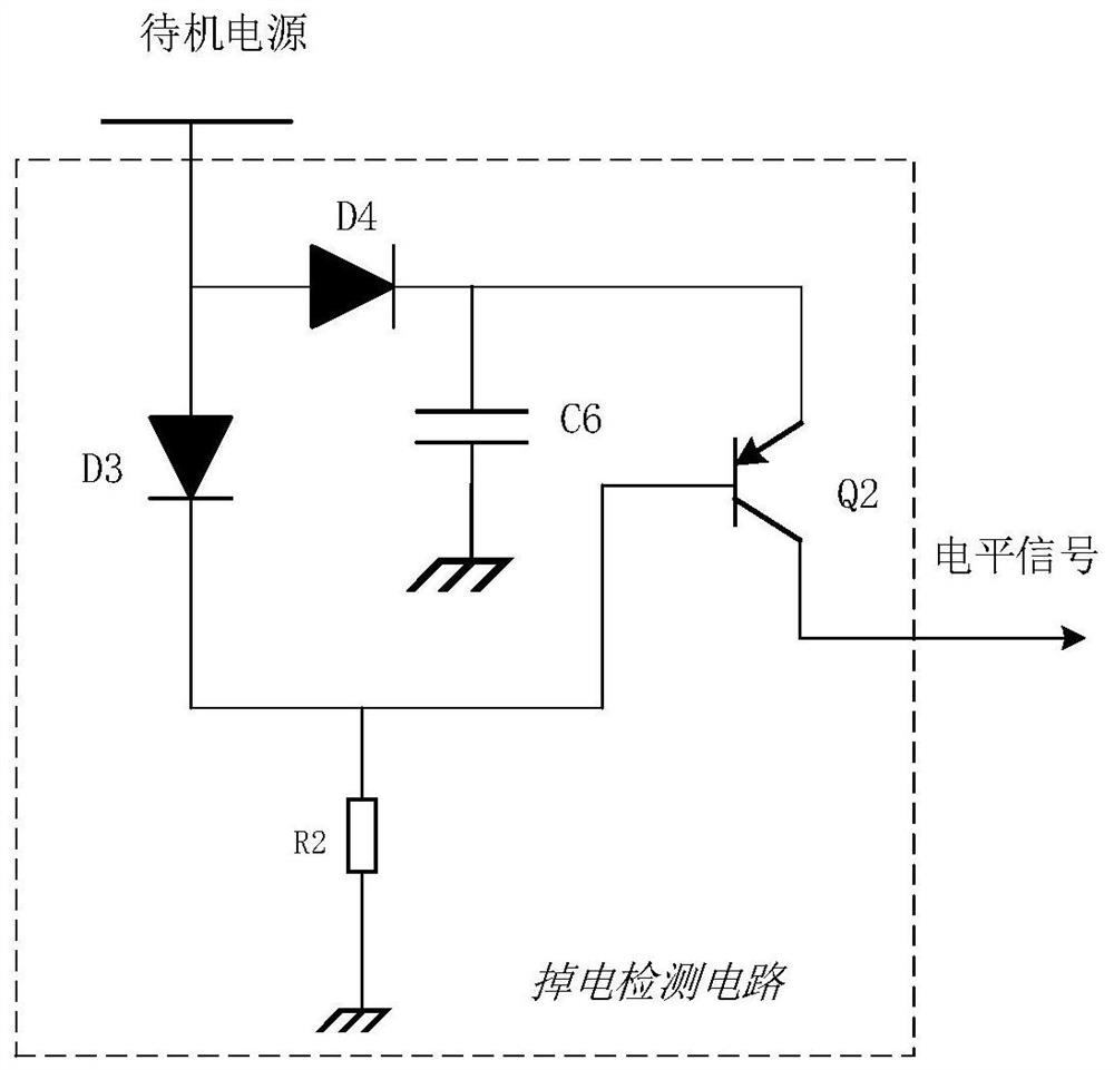
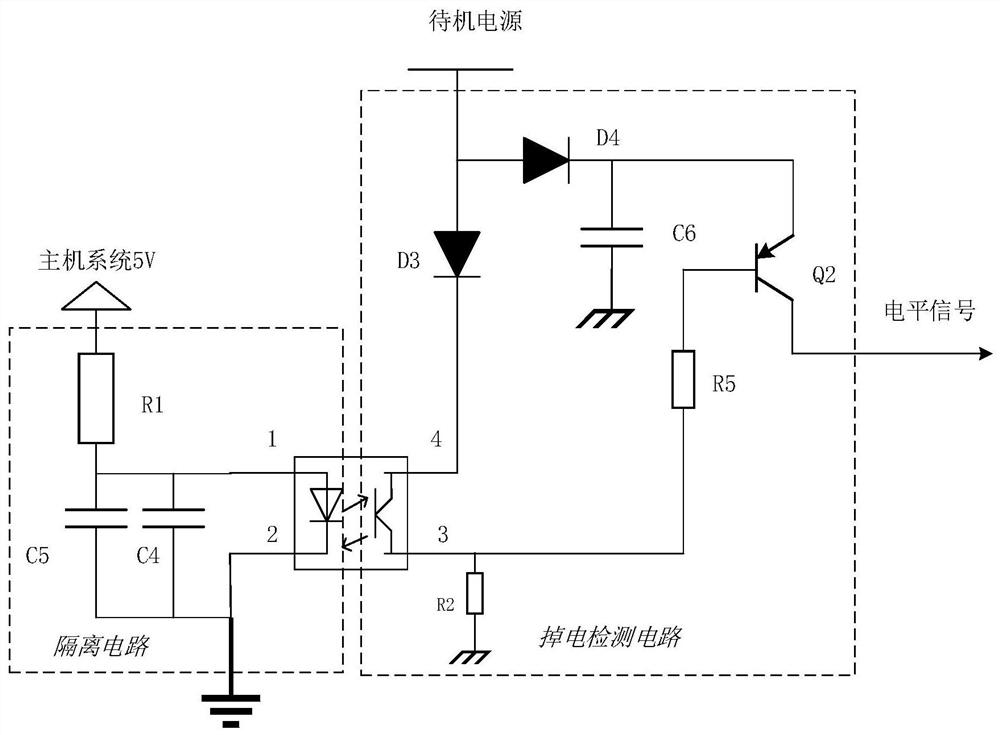
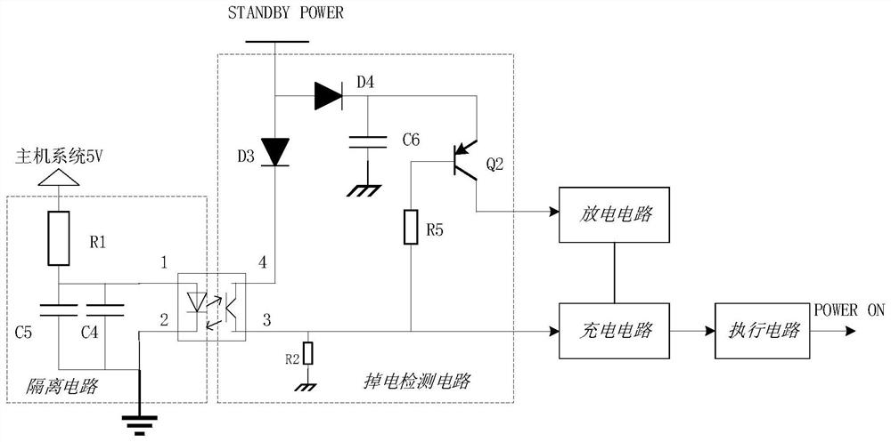
The invention relates to a power failure detection circuit, a power supply control circuit and audio equipment. The power failure detection circuit comprises a triode Q2, an energy storage capacitor C6, a diode D3 and a diode D4, the diode D3 is connected with the base electrode of the triode Q2, the base electrode is grounded through the resistor R2, and the energy storage capacitor C6 is connected with the emitter electrode of the triode Q2; the diode D3 is connected between the base electrodes of the triode Q2, and the collector electrode of the triode Q2 outputs a detection signal; in the power-on state, the standby power supply charges the energy storage capacitor C6 through the diode D4 and provides voltage for the base electrode of the triode Q2 through the diode D3. During power failure, the energy storage capacitor C6 provides voltage for the emitting electrode of the triode Q2, the voltage of the base electrode of the triode Q2 is reduced, and when the voltage difference is generated between the base electrode and the collector electrode of the triode Q2, the triode Q2 is conducted, and the collector electrode of the triode Q2 outputs a level signal; according to the scheme, quick detection of power failure is realized, power failure of the power amplifier can be controlled in time during power failure, and the power amplifier and the loudspeaker are protected.

Description

technical field [0001] The present application relates to the field of audio technology, in particular to a power failure detection circuit, a power control circuit and an audio device. Background technique [0002] In audio equipment, in order to protect the power amplifier and speakers, the delay start and power-off protection design are often adopted. When the system is turned on and off, the power amplifier is turned off and the speakers are muted to ensure that the impact signal of the power amplifier front stage does not occur. It will be amplified to the speaker, which not only ensures the safety of the power amplifier, but also protects the speaker from damage due to excessive impact signals. [0003] In the conventional technology, the general delay start and power-down technology are AC power detection, and the AC power as the power supply is quickly detected when it is powered on or powered off, and related shutdown and mute control are performed. In the audio eq...

Claims


Application Information

Patent Timeline
Patent Type & Authority Applications(China)
IPC IPC(8): G01R19/165G01R31/40
CPCG01R19/16547G01R31/40
Inventor 周跃兵陈雪兵
Owner GUANGZHOU AIMYUNION NETWORK TECH
Learn More