Refractory material spraying device and method

A technology of spraying device and refractory material, which is applied in the direction of spraying device, etc., can solve the problems of reducing the efficiency of power utilization, reducing the stability of fire resistance, and insufficient efficiency of coordination, so as to improve environmental protection and energy saving performance, improve uniformity, and improve efficiency effect

Pending Publication Date: 2022-07-22
苏伟
View PDF0 Cites 0 Cited by
  • Summary
  • Abstract
  • Description
  • Claims
  • Application Information

AI Technical Summary

Problems solved by technology

[0002] Refractory materials are used in various fields of the national economy such as steel, non-ferrous metals, glass, cement, ceramics, petrochemicals, machinery, boilers, light industry, electric power, and military industry. They are essential materials to ensure the production and operation of the above industries and technological development. It plays an irreplaceable important role in the development of high-temperature industrial production, but the existing refractory material spraying device has insufficient uniformity of spraying on the outside of the workpiece, which reduces the refractory stability of subsequent workpieces for use. At the same time, the refractory material The efficiency of the cooperation between the spraying device and equipment is insufficient, which reduces the efficiency of power utilization, increases the spraying time and reduces the spraying efficiency, and the sputtered refractory material is easy to pollute the environment after spraying on the outside of the workpiece, which reduces the efficiency of the equipment. environmental protection

Method used


Image

  • Refractory material spraying device and method
  • Refractory material spraying device and method
  • Refractory material spraying device and method

Examples


Embodiment 1

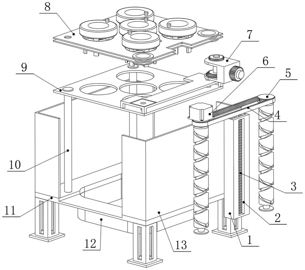
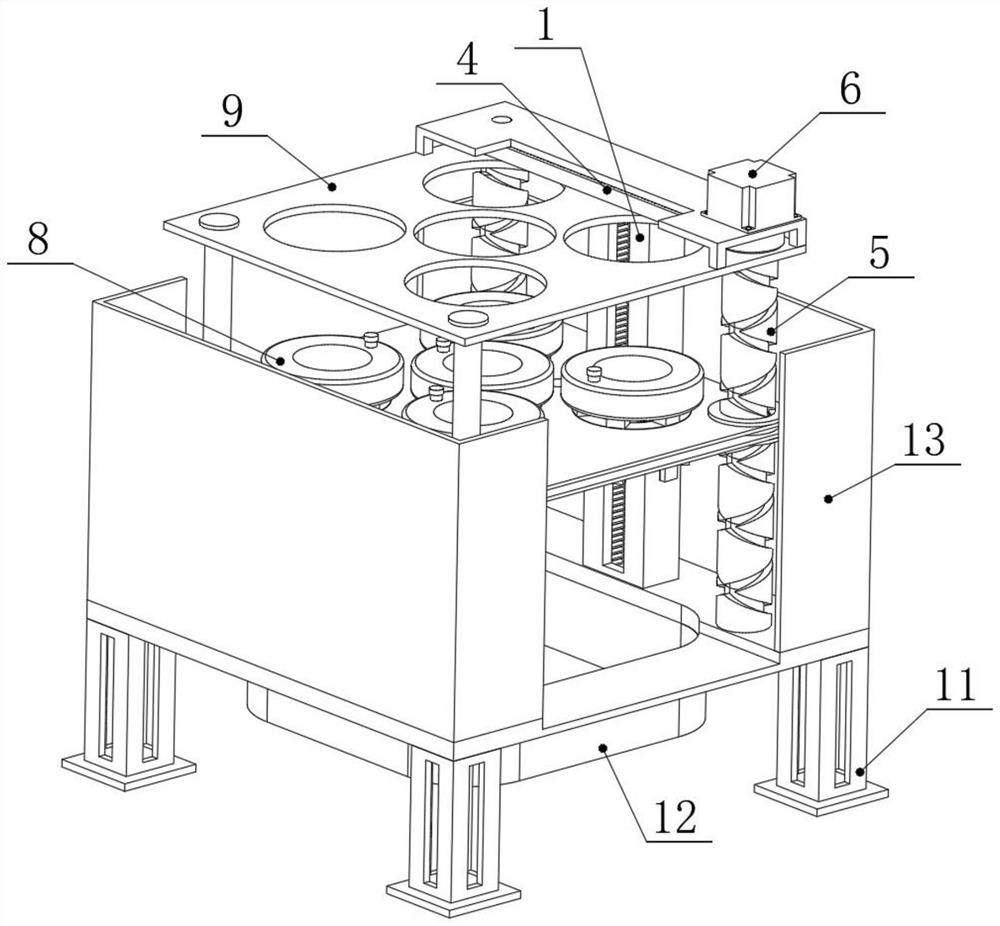
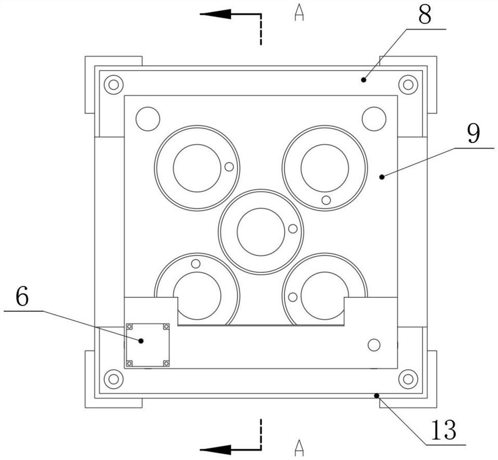
[0039] see Figure 1-12, the present invention provides a technical solution: a refractory material spraying device, including a connection card frame 11 for support, a guide sliding shaft 10 is symmetrically fixed on one side of the upper end face of the connection card frame 11, and is located in the connection card frame 11 The other side of the upper end face of the upper end face is symmetrically rotated and clamped with the guide device 5, and the top surfaces of the two sets of guide sliding shafts 10 and the two sets of guide devices 5 are fixedly installed with a support card plate 9, and the upper end face of the support card plate 9 is facing one of the groups. A servo motor 6 is fixed at the guide device 5, a guide slide 1 is fixed on the upper end surface of the connection card frame 11 near the middle of the two sets of guide devices 5, and a limit chute 2 is set on the inner end surface of the guide slide 1, and the connection card The upper end surface of the f...


PUM


Abstract

The refractory material spraying device comprises a connecting clamping frame used for supporting, guiding sliding shafts are symmetrically and fixedly installed on one side of the upper end face of the connecting clamping frame, and guiding devices are symmetrically and rotationally connected to the other side of the upper end face of the connecting clamping frame in a clamped mode; supporting clamping plates are fixedly installed on the top end faces of the two guiding sliding shafts and the top end faces of the two guiding devices, and a servo motor is fixedly arranged at the position, right facing one guiding device, of the upper end face of each supporting clamping plate. By arranging the supporting device, when the exterior of a workpiece is sprayed, the two sets of guiding devices can drive the supporting device to circularly move up and down outside the workpiece through the limiting device, and meanwhile the supporting device can rotate at a high speed when being driven by the transmission device to circularly move; and therefore, the spraying uniformity of the refractory material outside the workpiece is improved to the maximum extent.

Description

technical field [0001] The invention relates to the technical field of material processing equipment, in particular to a refractory material spraying device and a spraying method. Background technique [0002] Refractory materials are used in various fields of the national economy such as iron and steel, non-ferrous metals, glass, cement, ceramics, petrochemicals, machinery, boilers, light industry, electric power, and military industries, and are essential basic materials to ensure the production operation and technological development of the above industries. It plays an irreplaceable and important role in the development of high-temperature industrial production. However, the existing refractory material spraying device has insufficient uniformity of spraying the outside of the workpiece, which reduces the refractory stability of the subsequent workpiece when it is used. At the same time, the refractory material The efficiency of the cooperation between the spraying devic...

Claims


Application Information

Patent Timeline
IPC IPC(8): B05B13/04B05B12/32B05B14/00
CPCB05B13/041B05B13/0421B05B12/32B05B14/00
Inventor 苏伟
Owner 苏伟
Why Eureka
Try Eureka