
Method for controlling coaxiality between components

A control method and coaxiality technology, applied in manufacturing tools, metal processing equipment, metal processing, etc., can solve the problems of unsuitable high-precision equipment assembly, large error, low efficiency, etc., and achieve ingenious design, simple method, and improved The effect of running performance

Pending Publication Date: 2022-07-22
苏州保利格精密机械有限公司
View PDF0 Cites 0 Cited by
  • Summary
  • Abstract
  • Description
  • Claims
  • Application Information

AI Technical Summary

Problems solved by technology

[0003] At present, the coaxiality detection rod is used to determine the coaxiality, but this method has low efficiency and large error, and is not suitable for the assembly of high-precision equipment

Method used


Image

  • Method for controlling coaxiality between components
  • Method for controlling coaxiality between components
  • Method for controlling coaxiality between components

Examples


Embodiment Construction

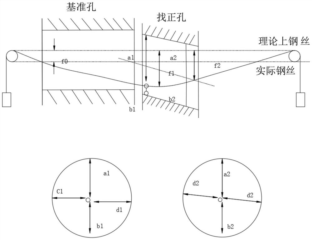
[0031] see Figures 1 to 2 , in an embodiment of the present invention, a method for controlling the coaxiality between components includes the following steps:

[0032] S1: Place the reference piece and the alignment piece on the same horizontal plane, use the steel wire to penetrate the reference hole and the alignment hole on the reference piece and the alignment piece, and the steel wire is parallel to the axis of the reference hole;

[0033] S2: Calculate the disturbance difference, and calculate the coaxiality error of the alignment hole through the disturbance difference;

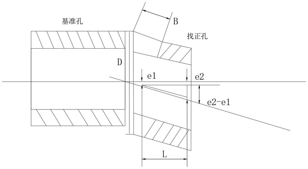
[0034] S3: Calculate the machining amount of the end face of the alignment hole according to the coaxiality error of the alignment hole;

[0035] S4: Adjust the alignment hole according to the calculated machining amount of the end face of the alignment hole, so that the alignment hole and the reference hole fit together to form a component.

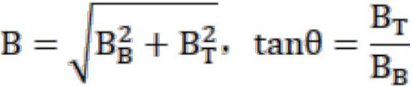
[0036] Further, the calculation formula of the disturba...


PUM


Abstract

The invention relates to the technical field of coaxiality control, in particular to a method for controlling coaxiality between components, which comprises the following steps of: S1, placing a reference piece and an alignment piece on the same horizontal plane, penetrating a steel wire through a reference hole and an alignment hole in the reference piece and the alignment piece, and enabling the steel wire to be parallel to the axis of the reference hole; s2, calculating a deflection difference, and calculating a coaxiality error of the alignment hole through the deflection difference; s3, the end face machining amount of the alignment hole is calculated according to the coaxiality error of the alignment hole; and S4, the alignment hole is adjusted according to the calculated end face machining amount of the alignment hole, so that the alignment hole and the reference hole are attached to form a component. The method is ingenious in design and simple, the machining amount of the end faces in the vertical plane and the plane is calculated through the coaxiality error of the alignment holes, the positions of the alignment holes are adjusted through a scientific method, the alignment holes are perfectly attached to the datum holes, the assembly precision of components is effectively guaranteed, and the operation performance of equipment is improved.

Description

technical field [0001] The invention relates to the technical field, in particular to a method for controlling the coaxiality between components. Background technique [0002] In the process of assembly and use of components, there is a need to meet the requirements of rotational flexibility after component assembly. When installing equipment, the hole or slide on the body is generally used as a benchmark to find the cylinder or the cylinder that is connected to the body. The holes on other parts make the two meet the technical requirements of coaxiality. [0003] At present, the coaxiality is determined by the coaxiality detection rod, but this method has low efficiency and large error, and is not suitable for the assembly of high-precision equipment. Therefore, those skilled in the art provide a method for controlling the coaxiality between components to solve the above-mentioned problems in the background art. SUMMARY OF THE INVENTION [0004] The purpose of the prese...

Claims


Application Information

Patent Timeline
Patent Type & Authority Applications(China)
IPC IPC(8): B23P19/10
CPCB23P19/10
Inventor 徐振保
Owner 苏州保利格精密机械有限公司
Learn More