End packaging method for assisting in forming I-shaped beam through long and thin soft mold

A technology of auxiliary molding and packaging methods, applied in household appliances, other household appliances, household components, etc., can solve the problems of increasing the risk of scrapping of flexible molds and parts, unqualified parts production, and bursting of sealing strips. Practical value, simple solution, and the effect of increasing the pass rate

Pending Publication Date: 2022-07-22
航天海鹰(镇江)特种材料有限公司
View PDF8 Cites 0 Cited by
  • Summary
  • Abstract
  • Description
  • Claims
  • Application Information

AI Technical Summary

Problems solved by technology

However, when this method fills the gap between the flexible mold and the metal tooling, a large amount of sealing strips and rubber will be consumed, and the price of these two materials is high, which is not conducive to cost reduction and efficiency increase; and the rubber blocks used in this method cannot It is effectively kept flush with the metal tooling base, which will easily lead to deformation of the soft mold and increase the risk of scrapping the soft mold and parts; in addition, the soft mold used for I-beam forming is a soft and slender tube made of composite materials For molded parts, the way of filling rubber and sealing strips between the soft mold and the metal tooling, if the sealing strips are not filled solidly, when curing and pressing, it is easy to be affected by the pressure and the sealing strips will be pierced by pressure to form channels and cause burst bags The situation, resulting in substandard parts production

Method used


Image

  • End packaging method for assisting in forming I-shaped beam through long and thin soft mold
  • End packaging method for assisting in forming I-shaped beam through long and thin soft mold
  • End packaging method for assisting in forming I-shaped beam through long and thin soft mold

Examples


Embodiment Construction

[0026] The technical solutions of the present invention will be clearly and completely described below with reference to the embodiments and the accompanying drawings. Obviously, the described embodiments are only the preferred embodiments of the present invention, not all the embodiments, nor are they intended to be used for the present invention. Any other form of limitation, any person skilled in the art may use the disclosed technical content to make changes or modifications and equivalent changes. However, any simple modifications, equivalent changes and modifications made to the above embodiments according to the technical essence of the present invention without departing from the content of the technical solutions of the present invention still belong to the protection scope of the technical solutions of the present invention.

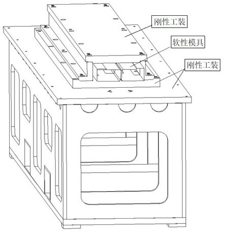
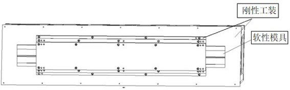
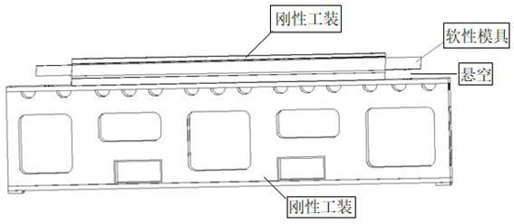
[0027] The present embodiment is a method for encapsulating an end of an I-beam assisted by a slender and flexible mold, comprising the followi...


PUM

PropertyMeasurementUnit
thicknessaaaaaaaaaa
thicknessaaaaaaaaaa

Abstract

The invention discloses an end packaging method for an I-shaped beam formed by a slender soft mold in an auxiliary mode, rubber and sealing rubber strip filling between the soft mold and a metal tool is canceled, a gap between the soft mold on the left side and the right side of an I-shaped beam part is filled with the sealing rubber strip, the sealing rubber strip is suspended along the bottom of the end of the soft mold, and a sealing rubber support is formed; sealing rubber strips are uniformly laid on the surface of the end part of the soft mold, and sealing rubber strips are also laid at the bottom of the sealing rubber support, so that the soft mold is completely sealed with the I-shaped beam part and the metal forming tool; and finally, an isolating membrane, a breathable felt and a vacuum bag are placed on the surface of the laid sealing rubber strip, the vacuum bag is sealed according to the position of the sealing rubber strip, and the sealing rubber strip is vacuumized and compacted. The use amount of sealing rubber strips and rubber is greatly reduced, the effects of reducing cost and increasing efficiency are achieved, the risk of bag explosion is eliminated, the production qualification rate of parts is increased, the scheme is simple, the effect is good, and the practical value is good.

Description

technical field [0001] The invention relates to a method for encapsulating an end of a slender and flexible mold to assist in forming an I-beam. Background technique [0002] I-beam, also known as I-beam, is a more common reinforcing structure in composite parts. It is divided into equal-section I-beam and variable-section I-beam and other structural forms. Thick and thin, some I-beam parts also have a hyperboloid structure. [0003] At present, the forming methods based on the autoclave process in the industry are basically metal core forming or soft die-assisted metal die forming. When the soft mold assists the metal mold forming, the original end package solution is to fill the gap between the soft mold and the metal forming tool with rubber and sealing strips to connect the soft mold and the metal tool to prevent the deformation of the soft tool. However, when this method fills the gap between the soft mold and the metal tool, a large amount of sealing tape and rubber ...

Claims


Application Information

Patent Timeline
Patent Type & Authority Applications(China)
IPC IPC(8): B29D99/00
CPCB29D99/0003
Inventor 林丽萍马秀菊孙成仲睿姚博卿吴青青王涛姚海涛邵雷华文龙
Owner 航天海鹰(镇江)特种材料有限公司
Why Eureka
Try Eureka