
Small nuclear magnetic resonance loading and unloading equipment

A technology of nuclear magnetic resonance and loading and unloading equipment, which is applied in the direction of transportation, packaging, and manual conveying devices. Drop damage, avoid sliding effects

Pending Publication Date: 2022-07-22
程苏丹
View PDF6 Cites 0 Cited by
  • Summary
  • Abstract
  • Description
  • Claims
  • Application Information

AI Technical Summary

Problems solved by technology

[0003] Small nuclear magnetic resonance instruments are precision equipment. When loading and unloading, it is necessary to minimize transportation vibration and keep them vertically placed at all times. However, most of the existing cargo handling equipment is a conveyor belt. When transporting goods, it is impossible to keep transporting objects at all times. In the vertical state, when the object is transported to the unloading end of the equipment, it will directly fall on the ground. When loading and unloading the nuclear magnetic resonance instrument, the loading and unloading personnel need to keep an eye on it at all times to prevent the unloading from falling and causing damage to the instrument. Therefore, the existing loading and unloading equipment cannot be used. The loading and unloading of nuclear magnetic resonance instruments, for which a small nuclear magnetic resonance loading and unloading equipment is proposed

Method used


Image

  • Small nuclear magnetic resonance loading and unloading equipment
  • Small nuclear magnetic resonance loading and unloading equipment
  • Small nuclear magnetic resonance loading and unloading equipment

Examples


Embodiment Construction

[0023] The technical solutions in the embodiments of the present invention will be clearly and completely described below with reference to the accompanying drawings in the embodiments of the present invention. The following embodiments are only for illustrative purposes and are not intended to limit the scope of the present invention.

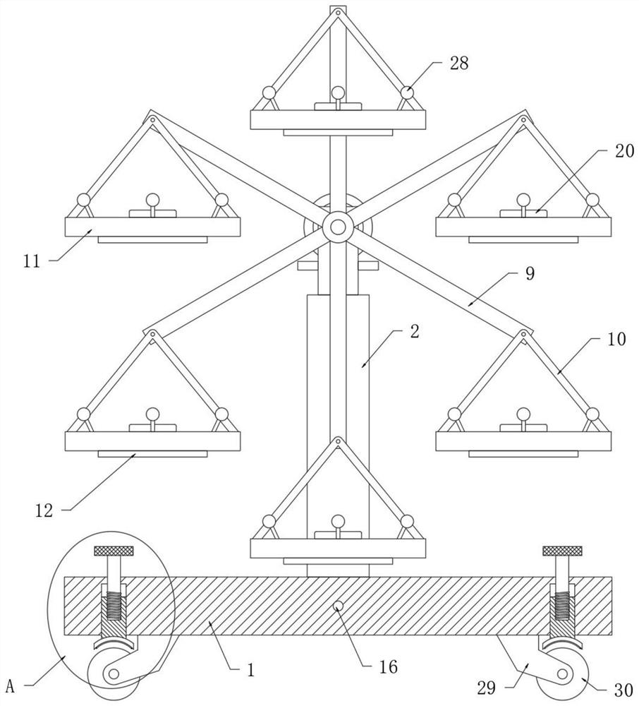
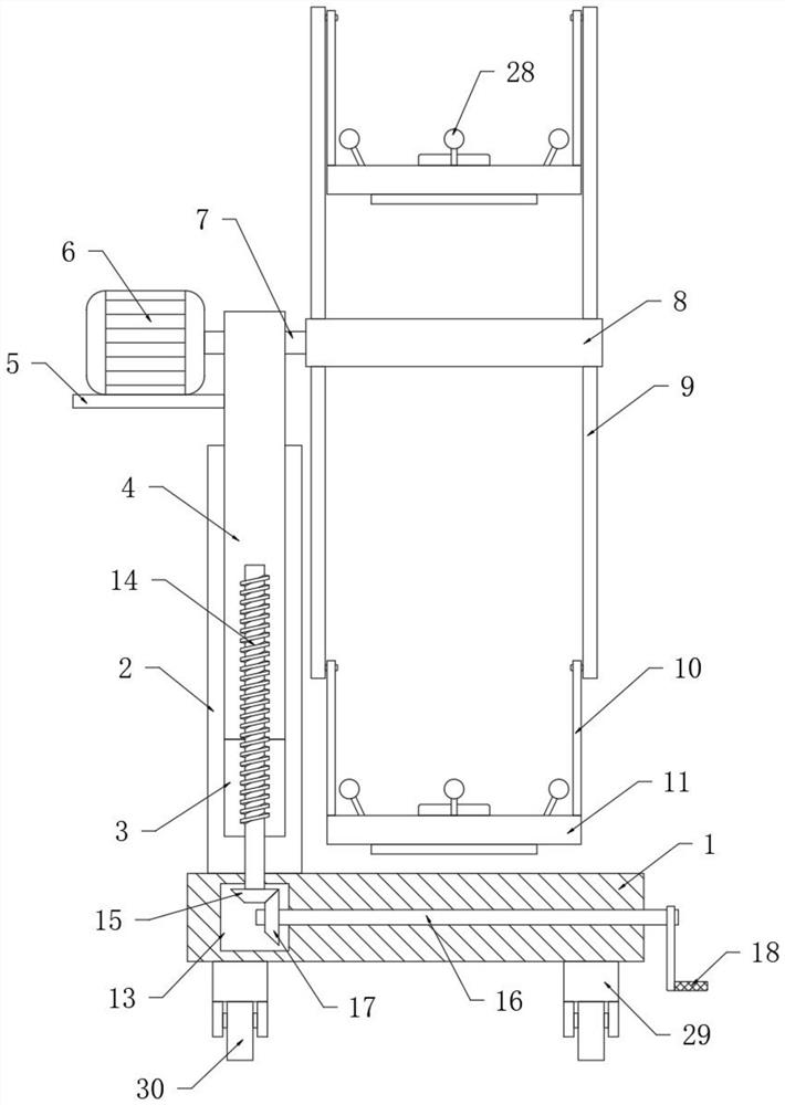
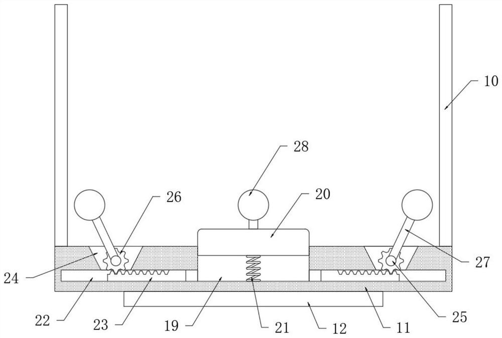
[0024] refer to Figure 1-4 , a small nuclear magnetic resonance loading and unloading equipment, comprising a support base plate 1, a support column 2 is fixedly connected to the side of the support base plate 1 at the center position, a lift slot 3 is opened on the support column 2, and a lift column 4 is slidably connected in the lift slot 3 , the upper end of the lifting column 4 is connected with a main shaft 7 through rotation, one end of the main shaft 7 is coaxially fixedly connected with a fixed cylinder 8, and the two ends of the fixed cylinder 8 are fixedly connected in a circular array. 9. One end away from the fixing cylinder 8 is...


PUM


Abstract

The small nuclear magnetic resonance loading and unloading equipment comprises a supporting bottom plate, a supporting column is fixedly connected to the side, located at the center position, of the supporting bottom plate, a lifting groove is formed in the supporting column, a lifting column is slidably connected into the lifting groove, and a main shaft is rotatably connected to the upper end of the lifting column in a penetrating mode; one end of the main shaft is coaxially and fixedly connected with a fixing cylinder, and the two ends of the fixing cylinder are fixedly connected with a plurality of pairs of connecting plates in an annular array mode. By setting the gravity center, an instrument on the bearing plate is always in a vertical state, when the instrument is carried and unloaded, the situation that the instrument falls off automatically due to the fact that unloading is too late is avoided, meanwhile, the gravity of the instrument and pneumatic transmission are used for keeping away, the four rotating rods can be automatically controlled to rotate towards the center of the instrument bearing plate, and the working efficiency is improved. The four elastic clamping balls are used for clamping the four sides of the instrument, so that the situation that the instrument on the bearing plate slides and is damaged due to falling during transportation is avoided, and the instrument is further protected.

Description

technical field [0001] The invention relates to the technical field of loading and unloading equipment, in particular to a small nuclear magnetic resonance loading and unloading equipment. Background technique [0002] Nuclear magnetic resonance is the physical process of atomic nuclei with non-zero magnetic moment. Under the action of an external magnetic field, the spin energy level undergoes Zeeman splitting, and the resonance absorbs radio frequency radiation of a certain frequency. The physical performance testing equipment in the subject area is convenient for students to vividly understand the physical mechanism of MRI from both theoretical and practical aspects, the actual setting and measurement of the basic parameters of MRI, and the methods of MRI. [0003] Small-scale nuclear magnetic resonance instruments are precision equipment. When loading and unloading, it is necessary to minimize transportation vibration and keep them vertically at all times. However, most ...

Claims


Application Information

Patent Timeline
Patent Type & Authority Applications(China)
IPC IPC(8): B65G9/00
CPCB65G9/004
Inventor 程苏丹
Owner 程苏丹
Learn More