
Auxiliary device for embedding steel sheet pile for pipe jacking construction

An auxiliary device, a technology for steel sheet piles, applied in sheet pile walls, infrastructure engineering, cleaning methods and appliances, etc., can solve the problems of steel sheet piles affecting the clearance size of shafts, sheet pile offsets, etc., to improve the scope of application and improve stability. The effect of stability and easy vertical clamping

Pending Publication Date: 2022-07-22
BEIJING MUNICIPAL CONSTR
View PDF1 Cites 0 Cited by
  • Summary
  • Abstract
  • Description
  • Claims
  • Application Information

AI Technical Summary

Problems solved by technology

[0004] When laying steel sheet piles, a crane is used to drive with a vibrating hammer. However, since the vertical state of the steel sheet piles is completely controlled by the vibrating hammer, the steel sheet piles are easily affected and shifted, causing the steel sheet piles to tilt and affect the clearance of the shaft. size

Method used


Image

  • Auxiliary device for embedding steel sheet pile for pipe jacking construction
  • Auxiliary device for embedding steel sheet pile for pipe jacking construction
  • Auxiliary device for embedding steel sheet pile for pipe jacking construction

Examples


Embodiment 1

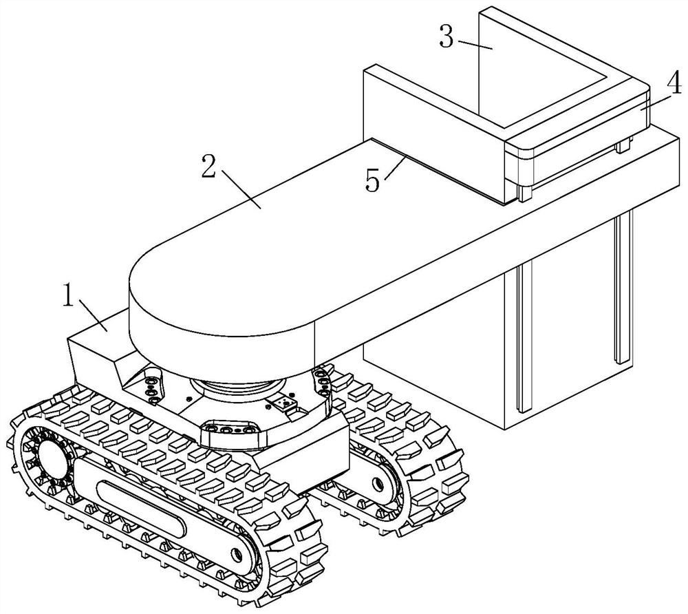
[0031] like figure 1 As shown, an auxiliary device for burying steel sheet piles for pipe jacking construction according to the embodiment of the present invention includes a crawler chassis 1, a beam 2, a C-shaped guide plate 3 and a lifting mechanism 4; the middle of the top surface of the crawler chassis 1 rotates A beam 2 is installed, and a notch 5 is opened on the side of one end of the beam 2 away from the crawler chassis 1, and a C-shaped guide plate 3 is slidably installed inside the notch 5. The C-shaped guide plate 3 and the inner wall of the notch 5 A lifting mechanism 4 is arranged between the pilings; during operation, the crawler chassis 1 moves to the position to be piled up, the motor drives the beam 2 to rotate, and drives the C-shaped guide plate 3 to move to the piling point. After the lifting mechanism 4 drives the C-shaped guide plate 3 to slide down , so that the C-shaped guide plate 3 touches the ground, the crane lifts the steel sheet pile to the middle ...

Embodiment 2

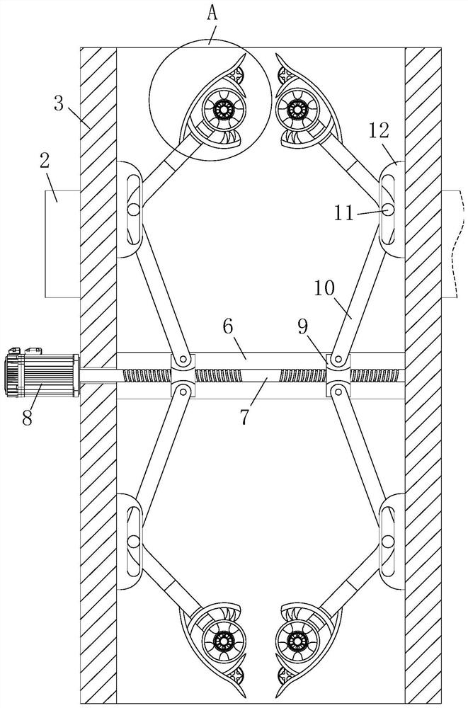
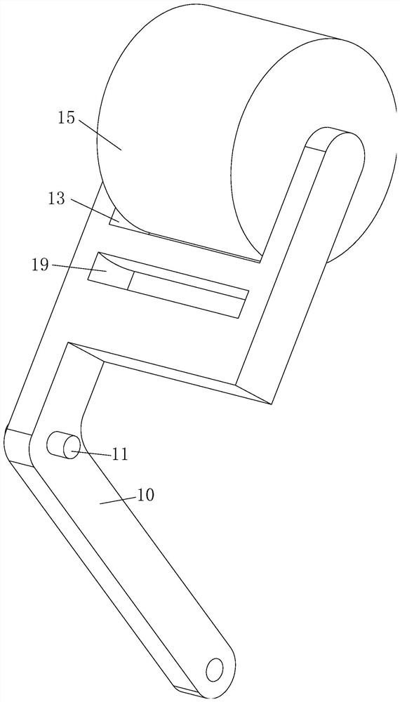
[0041] like Figure 8 As shown in the comparison example 1, another embodiment of the present invention is: the outer rings at both ends of the support rod 14 are fixed with helical blades 34, and the outer rings of the helical blades 34 are connected to the pressure roller 15. The inner ring is slidingly matched, and the outer wall of the spiral blade 34 is provided with fluff; during operation, the pressing wheel 15 rotates, so that the spiral blade 34 rotates against the inner wall of the pressing wheel 15, and pushes out the soil entering the pressing wheel 15, thereby improving the The degree of cleanliness inside the pinch roller 15.

[0042] When working: the crawler chassis 1 moves to the position to be piled, and the motor drives the beam 2 to rotate, driving the C-shaped guide plate 3 to move to the piling point, and the lifting mechanism 4 drives the C-shaped guide plate 3 to slide down so that the C-shaped guide plate 3 contacts To the ground, the crane hoists the...


PUM


Abstract

The invention belongs to the technical field of foundation pit supporting engineering, and particularly relates to an auxiliary device for embedding a steel sheet pile for pipe jacking construction, which comprises a crawler chassis, a cross beam, a C-shaped guide plate and a lifting mechanism, a cross beam is rotatably mounted in the middle of the top surface of the crawler chassis, a notch is formed in the side face of the end, away from the crawler chassis, of the cross beam, a C-shaped guide plate is slidably mounted in the notch, and a lifting mechanism is arranged between the C-shaped guide plate and the inner wall of the notch; during working, the crawler chassis moves to the position where piling is to be conducted, the motor drives the cross beam to rotate and drives the C-shaped guide plate to move to a piling point, then the lifting mechanism drives the C-shaped guide plate to slide downwards, the C-shaped guide plate makes contact with the ground, the crane lifts a steel sheet pile to the middle of the C-shaped guide plate, and the vibration hammer vertically drives the steel sheet pile into the ground along the C-shaped guide plate. Therefore, the perpendicularity of steel sheet pile construction is guaranteed, and the situation that the clearance size of the vertical shaft is affected by the perpendicularity of the steel sheet piles is reduced.

Description

technical field [0001] The invention belongs to the technical field of foundation pit support engineering, in particular to an auxiliary device for burying steel sheet piles for pipe jacking construction. Background technique [0002] Larsen steel sheet pile is a commonly used sheet pile cofferdam, which was first used in the foundation construction of bridges. It has the advantages of light weight, high strength, tight lock, good water tightness, high safety, and simple construction and short construction period, so steel sheet piles have a wide range of uses in deep foundation pit support. [0003] A Chinese patent with publication number CN110565636A discloses a steel sheet pile construction method, including the following steps: step 1, mark the position of each pile position on the construction ground; step 2, move the rotary drilling rig to the position of the corresponding pile position Rotary drilling is carried out, and after drilling to the preset pilot hole depth...

Claims


Application Information

Patent Timeline
Patent Type & Authority Applications(China)
IPC IPC(8): E02D13/04E02D5/04E02D17/04B08B1/00B08B1/02B08B9/023
CPCE02D13/04E02D5/04E02D17/04B08B9/023B08B1/20B08B1/165
Inventor 任利民洪保鑫王乐鲍金涛陈伟罗敏孝吕跃东刘向东刘明华
Owner BEIJING MUNICIPAL CONSTR
Learn More